
The first part of my little treatise on Basic Hull Construction dealt with building ship model hulls from scratch for radio control. This part is a little different because most of you reading this probably do not build ship models solely for radio control. I suspect most of you also build ship models for static display as well. I say that because, right off the bat, I think as most of you read this you will think this article is directed at construction of hulls for static models. Not true.
It is true that this is an outstanding method of building model ships for display, but it also works very well if you plan to use it to make a mold for fiberglass, resin casting, or vacuform hulls. In fact, you could even use this method for the radio controlled ship model itself.
The method I am about to show you is actually a modified version of the old "bread and butter" method. It will work for any size, scale, or type of hull, and will yield wonderful results. I have used this method for years in my business (Cottage Industry Models, Ltd.) to create the hulls for my cast resin ironclad kits in 1/96th scale. I did not create the method, and forget where I saw it, but loved it from the moment I first tried it.
For the sake of this article I will focus on the primary hull of a Confederate Ironclad kit I am producing now. I won't delve into any of the other parts of building the ship since most of you probably already know all about that part. This method is a little less advanced than the one shown in Part 1 but it really requires you to have, or have access to some decent precision wood shop equipment.
FINALLY!!! A decent set of plans to work with! Oh Joy and Happy Day! Now for the wet blanket; check them anyway.
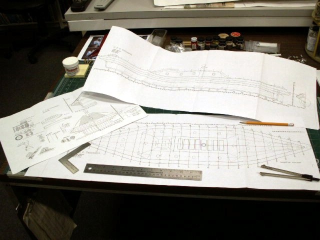
Use your dividers to make sure the overhead views all match widths measured from the centerline. Believe it or not, many plans with "lifts" shown are of different widths on the left and right side of the centerline, even though they are supposed to be at the same level. Ok, don't get me started on plans again. Suffice it to say you need to make sure all of the cross sectional views match the overhead views, and that they all match with the profile views at every point. That means measure BOTH sides from the centerline and from the baseline.
Make sure the baseline is straight. In this specific case, the baseline of the ship's profile view is actually bent upward near the stern by almost ¼". I had to draw a new baseline, and adjust the next level of the hull between the lower hull and the middle hull. (More on that part later) As a rule, I have never seen any ship with a keel that bends upward. Keels between the upright perpendiculars are always straight. If someone knows of a ship where that is not the case I would love to hear about it.
As you check the hull cross sections with the rest of the plans you should also be looking for any indication of hull symmetry being out of whack. There may be cases where it just does not look right to your eye. Make a note of it and try to look at photos of the ship out of the water if they are available. Many times you will figure out why you were not sure of a particular issue. After all, a picture is worth a thousand words. The big thing is to make sure you absolutely understand the shape of the hull as laid out.
Decide now where the best places will be to break down a complex hull into smaller more manageable pieces to work with and shape.
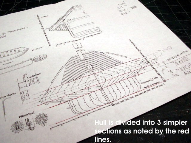
As you can see, Confederate Ironclads had some very confounding angles when taken as a whole. Trying to carve something like this from a single block would probably cause me to use a lot of foul language and accomplish nothing. Instead, I have broken the hull into three parts, the lower hull, middle hull, and main deck. The cross sectional view of the plans shows how I decided to divide the hull with red lines drawn across the plans. (Keep in mind that because I am making this into a kit I also have to think about where to have the mold seams that a model builder has to remove. I need to keep this simple for them to preserve surface details)
Once you have decided how many sections there will be to the hull you will need to calculate how many lifts of wood will be needed to make up each section. The rule of thumb here is to use more layers of wood as the hull becomes more complex, and has more compound curves. For example, in this case the Lower Hull is not very complex by itself, and measures 15/16" thick from the baseline to the underside of the middle hull. I decided to use ½" thick wood laminated to ¼" laminated to 3 layers of 1/16" thick wood. The thinnest layers were for the bottom of the hull because that is the area on this ship where most of the curves were. The thicker ½" stock was on top where it would join with the middle hull because that part was straight up and down. So you should try to use as many layers of wood as you can as your hull lines become more complex. If I were doing the plug for making a vacuform hull of a lifeboat I would probably use layers of 1/16" wood because that type of hull has many compound curves all along its length.
The last step here is to go to the copy store and get several good copies of your plans (have you checked them for accuracy yet?) that you can cut up to use as patterns. These patterns will be glued directly to the wood blocks you are about to create to make the basic rough cutouts that will be sanded into final shape. You should also buy yourself a can of spray adhesive, a can of flat black spray paint, and a bottle of wood glue or some other type of SANDABLE glue. You will need to get at least 1 copy for each section of the hull. In this case I bought 3 copies of the lift plans, and 1 for the outboard profile.
Now figure out which sheets of wood go with each of the sections of hull you want to build. Check them against your plans to make sure they all fit, and will give you enough wood to glue your patterns to with a little extra. Sort them into their appropriate groups, and spray one side of each board with your flat black paint.
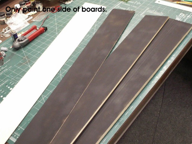
Make sure it is heavy enough to cover completely, but not so heavy as to soak the wood. Also make sure the humidity is not high. It will warp your sheets of wood in just a few minutes if you are not careful.
While the paint is drying you can go back and start cutting out your patterns. Be sure to cut out each of the lift patterns slightly OUTSIDE the lines you need to reduce the wood to. Don't try to cut the pattern to the exact size you need. Believe me it is much easier to sand and shape the block down to its final size than cut everything so precisely.
One other item that is important is a perfectly flat place to clamp everything while you are laminating the wood blocks. I built a special clamping device that I went to a great deal of trouble ensuring was true and square.
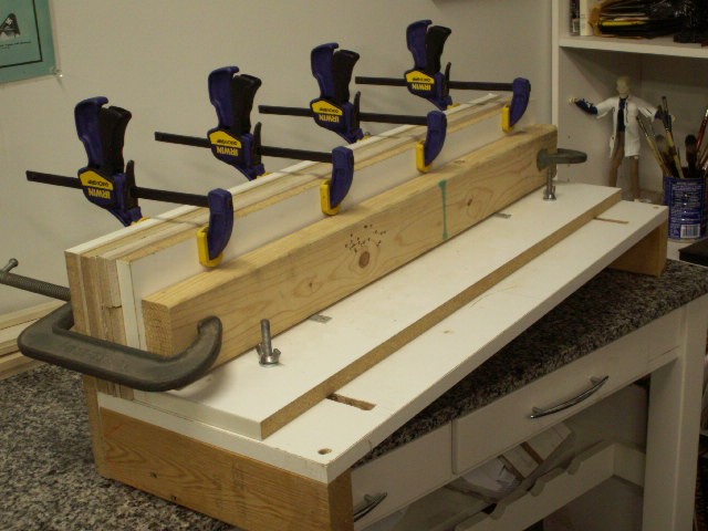
A good flat worktable will work fine, but you do need a bunch of clamps.
Now we start gluing and clamping. Since I have done this a time or two I feel frisky enough to do all the sections at once, but you may want to do each one separately. If you do more than one section at a time you should use a sheet of plastic food wrap between each section so the glue that squishes out will not glue your multiple blocks into one big one. Yes, I have done that. You may also want to put a layer of plastic down between the blocks you are making and the table so you don't build yourself a useless piece of furniture. Yes, I have done that too…very depressing.
Put the glue down on a board. STOP!!! Yes, it matters how you start this process. The best way is to put glue down on the thickest board and work your way down to the thinnest boards. Applying glue to the thin boards starts them to warping almost immediately. The boards should also be arranged so that a painted side is laminated to an unpainted side. The last two faces of wood will both be painted and glued to each other. The outer layers will be unpainted when you are done. This process will help keep the wood from warping too much as you work, because as soon as you put glue on that wood it will soak in and bend it like a fishing pole. So work fast. It helps if you use a paint roller or brush to spread out the glue evenly over the board. Lay the next board down on the one you just applied the glue to, and start putting down glue for the next one until you are finished.
When all the boards are glued together move the block over to your clamping area and clamp the block tightly. Glue will squirt out and you can wipe that away with a damp rag. Try to make all the clamps apply the same pressure across the whole block. Make sure all the boards are stacked neatly and as close to evenly as possible. Let it dry at least 24 hours.
After the glue has dried remove the block from the clamps. This is the point where you need to have access to some wood shop machinery. You need to square up and clean the rough parts and dried glue off the sides and top of the block. Once the block has been trued up you need to mark one end of the block with a pencil across the centerline.
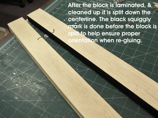
This will tell you which way the block is to be oriented when you glue it back together again. Cut the block right down the centerline and clean up the matching faces of each half. Paint each face as you did the layers with flat black paint, and when the paint is dry glue the block back together again and clamp it well. Make sure you align the mark across the centerline.
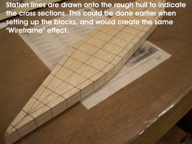
When the block is dry again remove it from the clamp and clean it up one more time. It needs to be smooth and square all the way around. If you have not figured it out yet this method will now give you a block of wood to carve and shape your hull from that will ALWAYS have a true centerline from which to place templates and take measurements. No more re-drawing and worrying about whether or not you are off the mark. You will find out, as you carve away at the hull, the lines of each lift of wood will also come out. As you work your eye will be much more able to see any dips or high spots, or areas that are just not shaped correctly.
Another point is that, if you feel like it, you can also cut your block across the centerline at each of the bulkhead locations shown in your plans, and repeat the painting and re-gluing process. As I mentioned before in Part 1, the more points you have in your hull for reference the more accurate it will be in the end. With this method you will be able to see your hull take shape as if you had a computer generated wire frame model in your hands.
Patterns:
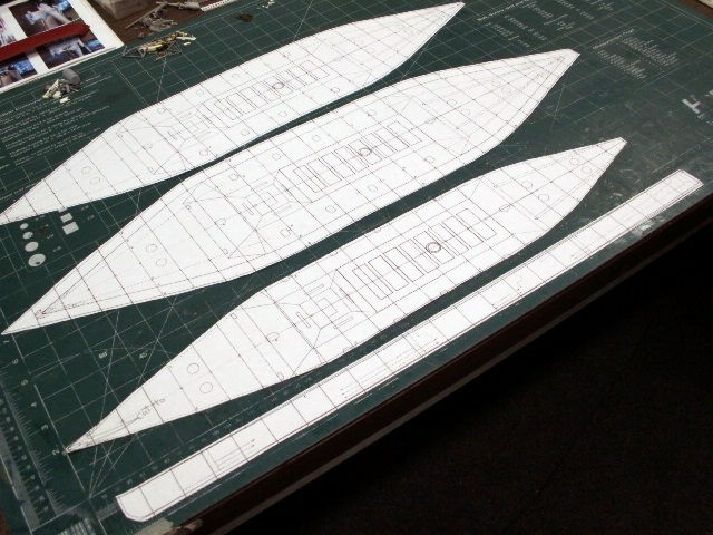
Use your hobby knife to cut out the overhead view of your plans (copies) (we need to cut out the block from the overhead view first, then we will make the profile cut), and make sure you cut outside the lines. You will need one complete overhead cutout for each of the main sections of the hull.
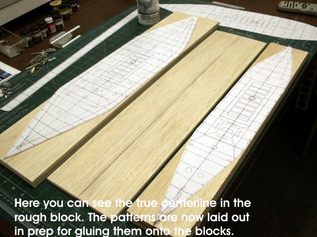
Be sure you understand which lifts go to which block, or section of the hull. You should also cut out a set of cross-sectional templates, as shown in "Part 1." These will help you in final shaping.
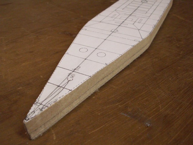
Once the lift patterns are cut out you can use spray adhesive or a glue stick to attach them to the blocks. Be sure to align the centerlines on the templates to the centerlines of the blocks, and try to not have any wrinkles in your template.
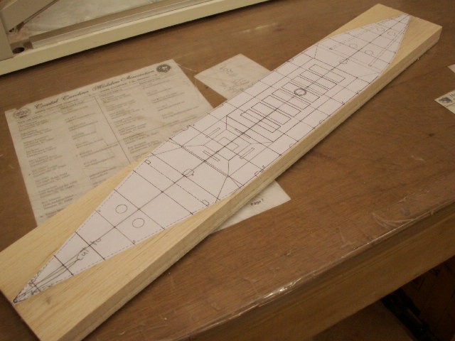
Use a bandsaw to cut out the shape of your hull, and stay outside of the lines on the template. When the rough hull is cut out you need to carefully sand it smooth along the cut lines until you reach the lines drawn on the template.
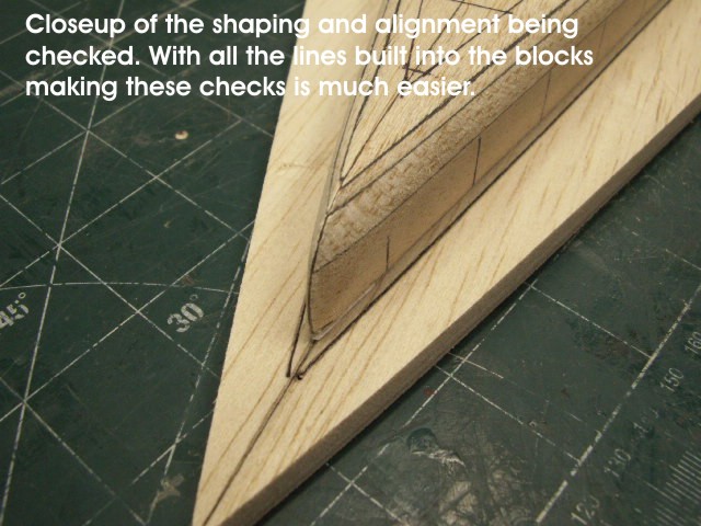
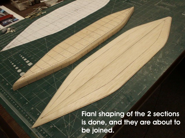
Next, you need to cut out and apply the profile template to your rough hull, and make the profile cuts. Carefully sand it to fit the shape of the template. From here on you can begin sanding and shaping your hull into its final shape. Be sure to use your cross-sectional templates to check the shape as you work.
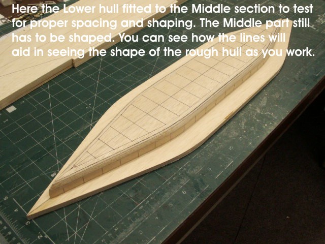
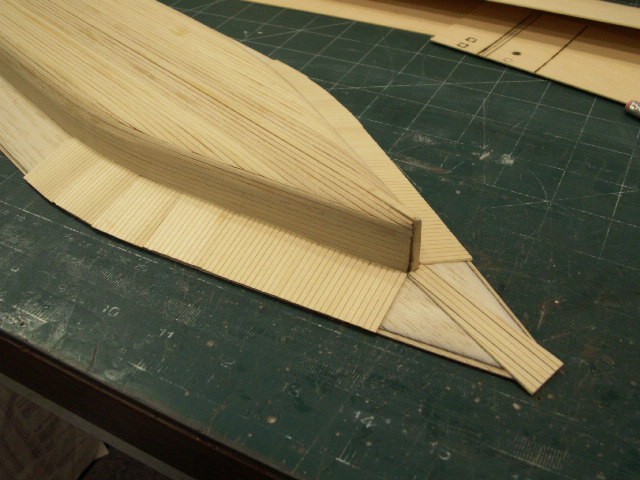
As you shape your hull parts, assuming you have more than just one hull section as I have in this example, test fit each section to the other by stacking the hull sections on top of each other, and aligning the centerlines and other marker points. You can see that I used a black pen to draw other lines on my hull that I used later to help me apply planking.
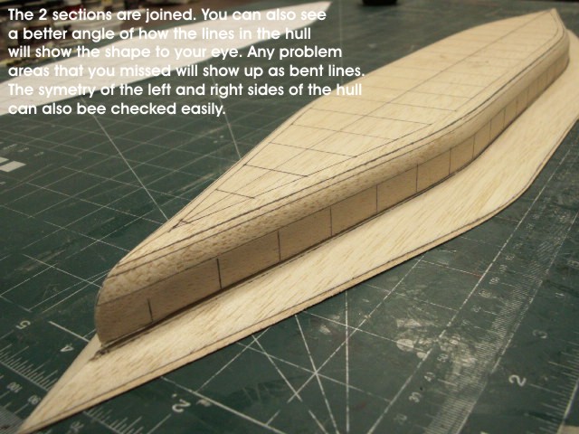
When you finish making all the sections of the hull you can join them together. In this case I have joined the Lower Hull to the Middle Hull to create the entire Lower Hull assembly for my ironclad kit. I did not join the last section because it will be the main deck for the model, and needs to be cast as a separate piece.
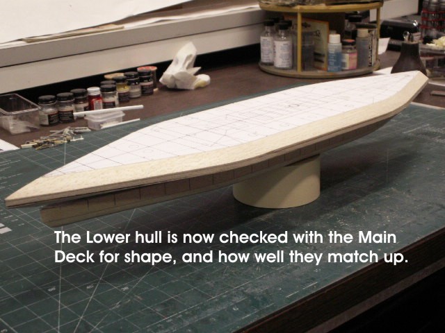
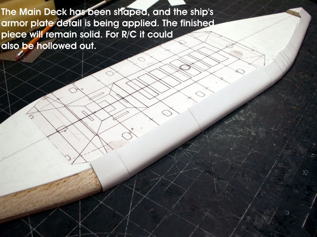
The Main Deck piece will be one solid mass of resin in the final kit. However, before I produce the Lower Hull into a resin copy I will hollow it out. You can see that I have also applied planking to the Lower Hull and simulated armor plates to the Main Deck.
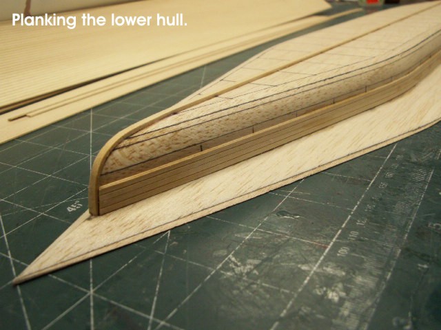
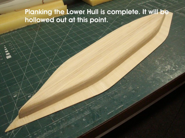
If you decide to build a hull in this manner for R/C, I recommend you seal the hull parts with resin, and apply any outside details such as planking before you try to hollow out the hull. This planking should help ensure nothing comes apart as you do the hollowing. In my case, I used an "X/Y" table with a router bit in my drill press to do the job. The fact that you will always have a true centerline no matter how deeply you cut into the hull means you never have to worry about losing your mark, and winding up with a misalignment somewhere when it comes time to fit the hull sections together.
If you decide that doing a fiberglass hull is the way to go, well…Great! Join the hull sections together, blend the seams and do any final shaping, and seal it all with resin. You will need to sand, and fill many times before you reach the stage of getting a plug that is ready for a fiberglass mold, but at least it will be accurate and solid (which is nice, as it helps prevent bowing or twisting of the plug over time).
Is vacuformed plastic your cup of tea? Nice choice, and frankly, one of my personal favorites. Just join the sections that need to be joined, i.e. the Lower and Middle sections to create the Lower Hull. Now build a vacuforming table that will fit the plug and have fun. I have done this process on my Palmetto State kit (See Gallery 2, C.S.S. Palmetto State) for the casemate and lower hull. After I had a decent hollow plastic vacuformed hull I scribed all the armor plate details and planking into them, and made the rubber molds as I normally would have. This method produces a very lightweight easily modified plastic hull that can be stiffened with internal framing for R/C that will last forever.
Conclusion:
I know this method may be re-hashing old information, and I don't mean to bore you with it. However, in all my travels and observations of ship model building methods I have never seen anyone promote this particular way of producing a hull. I have listened many times to people talk or write about building a hull, and all the time it took for them to shape and finish it, and how careful they had to be in the process. Yet, None of them seem to have ever thought about doing it this way. Maybe it is the extra trouble of laminating the blocks, or whatever, but if you think about it, the amount of time you spend producing a block to carve a hull from this way actually reduces the amount of time you spend in the long run because of the built-in visual references that you will not have to keep plotting on a plain block of wood.
I realize that most of you will not carve a hull from a solid mass. You will probably buy a kit or a commercially produced hull. However, I am also sure that many of you, at some point, will want a model of a ship that can only be built from scratch. With this in mind I felt that offering you a simpler twist on an old idea might just be the inspirational kick you need to try something new. You should not forget that this method can be used for almost any construction from a solid mass where precision shaping is an issue, not just for hulls. I have used it for superstructure parts, and small ships' boats. I have used it for various plugs for my resin casting business and other modeling projects.
The greatest benefit I can think of from this method is consistent precision reference points built into your modeling medium. No more guesswork about true centerlines, or redrawing of marks. I hope it will benefit all of you at some point. I felt that it is something that should merit being passed on to others to help simplify their efforts. Good luck!
William Blackmore is owner of Cottage Industry Models, a manufacturer of resin Civil War era ship and gun emplacement kits.

Back to Construction Articles
722 vists so far.
Version
1.1 08/11
![]()