
One of the most daunting problems for "newbie" ship model builders interested in starting their own R/C fleet can often be constructing a hull for their ship model from scratch. The reasons for doing so may vary from simply wanting to "do it yourself", to not being able to find a commercially available fiberglass hull of the ship you want to build. Regardless of the reason, building the hull is often something the novice modeler very much wants to do, but also very often finds overwhelming because of a lack of specific information laid out in a logically enumerated way. This article is aimed directly at the novice builder, and I hope this little treatise will help you accomplish your goal.
Before you begin, you will need to have certain tools. In addition to the usual woodworking tools (saw, sander, hobby knives), I recommend the following:
The very first problem you will face is plans. In all the years of model ship building, and production of model ship kits that I have had I have never run across a set of ship model plans that can be fully trusted for accuracy. I have some plans that are very thorough and complete, but even the best plans in the world should be cross-referenced with photographs, and checked carefully with all manner of measuring devices. In some cases those drawing the plans simply do not care about accuracy. Case in point, I once had a commission to build a New Orleans class cruiser. I bought two sets of commercially available plans and a technical reference book about the ship itself. When I laid out the plans I instantly found that the hull at the stern was completely misrepresented in the cross-sectional view, and had nothing to do with how the ship actually looked. I later found that the various deck layouts and bridge levels were not only wrong, but also, did not line up correctly when stacked up, were the wrong shape, and, unbelievably, contained elements of the ship as she appeared in 1944 incorporated into the 1942 version. The most insulting part was that a technical book was easily available from the same dealer, who also drew the plans, and all he had to do was look at the book!!
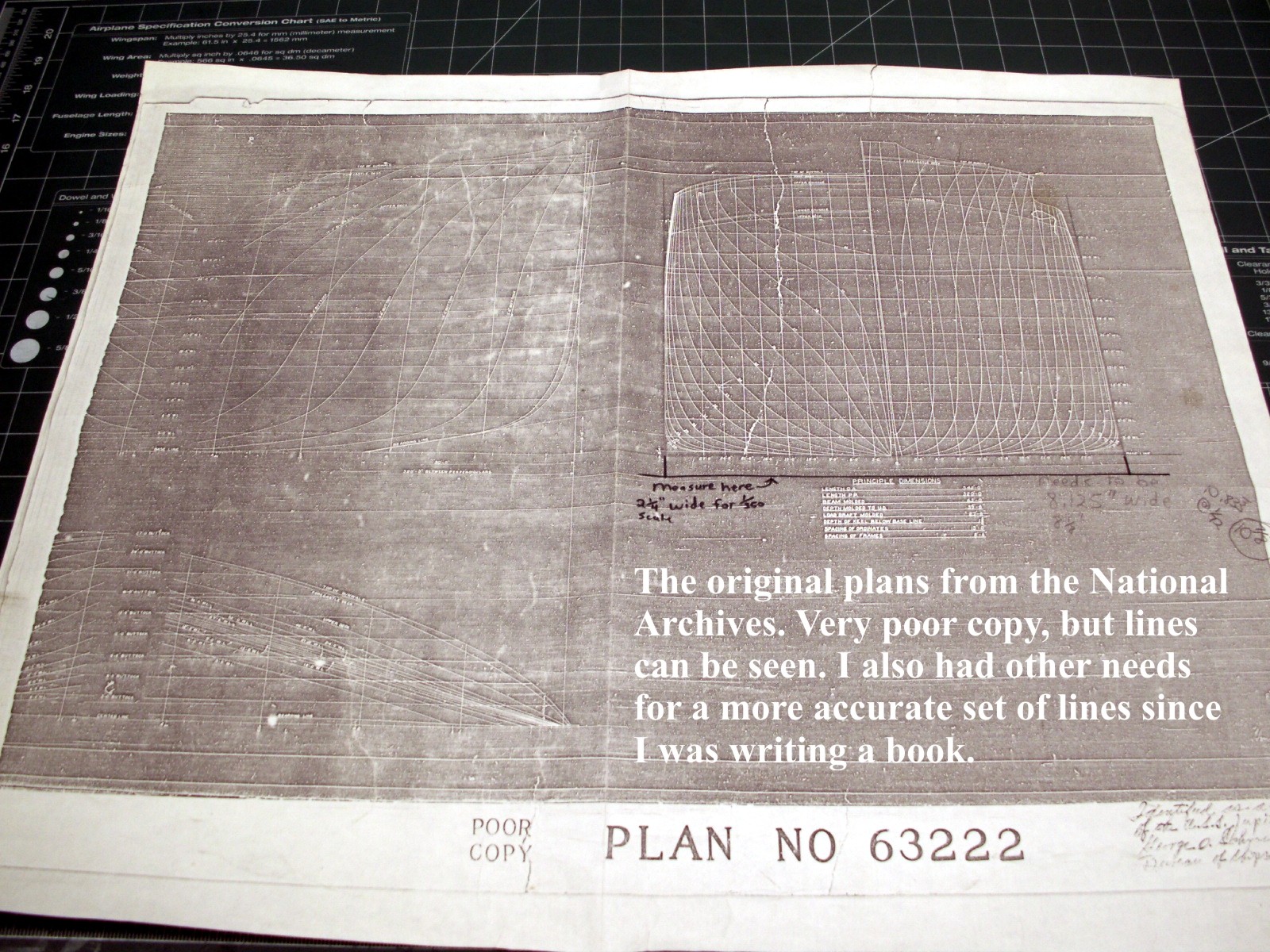
You may also run into a situation where some sets of plans of the same ship (especially from the National Archives) are sent to you showing the various views in different scales. They may be in very bad shape and almost unreadable.
Click on any photo to view a larger version
You should remember that these folks have to process thousands of orders each year for ship plans and getting them to an exact scale is not on their list of stuff to do. You will have to take care of that part yourself. In the worst case scenario you may even have to partially re-draw those plans yourself. It is not hard to do, but can be a major pain in the butt.
From here on I am writing with the assumption that you are working with a really decent set of plans. The only exception will be that I will cover a little bit about what I had to do to re-draw my plans for the hull of the U.S.S. Langley CV-1, the ship I am going to use to illustrate this essay.
In April of 2008 I decided to start building the only R/C model of the U.S.S. Langley CV-1 that I know of, and since I am also writing a book about the ship's technical history and had all the plans a man could hope for on the ship, I felt building a model should be a piece of cake. Well, as the saying goes, "If you want to make God laugh, just tell him your plans." When I began checking the plans, most of which came from the National Archives, I found several of the aforementioned problems. The first of which was that the cross-sectional views did not match the profile, or "Sheer" plan views when checked with a pair of dividers even though they were drawn on the same page!!! The second problem, which is common, was that the plans were in very bad shape and almost unreadable. The final problem was that when scaling out everything ,the sheer plan not only failed to match the cross-sectional views, but also failed to yield a model of the correct length when laid out. This is a very typical situation for scratch builders, so here's how you fix it.
Take a deep breath, stop cussing, and throwing things across the room.
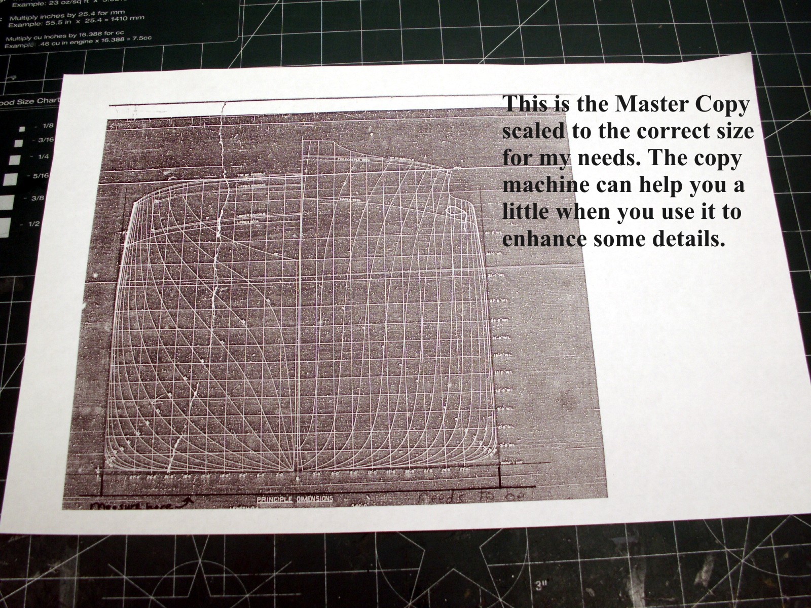
First, make sure that you have all the available information and plans out there about your subject. Assuming you do, get a notepad and start writing down the important information about the ship that the actual Builders put in the plans. Ship's length overall, width, and spacing between the frames, etc. Sometimes the guys who drew the plans will put the spacing between the cross-sections on there as well; in my case it was 13 feet. Also make a note about any special construction details of the ship noted in the plans. Double check that your plans are all correctly scaled to the correct size for the scale in which you are working. You may have to cut the plans apart and have them scaled properly on a copier in order for them to be correct, and each section may actually have to be copied at different percentages.
If all this is correct and all your plan views of the ship work out when measured carefully then it is time to assemble a building board.
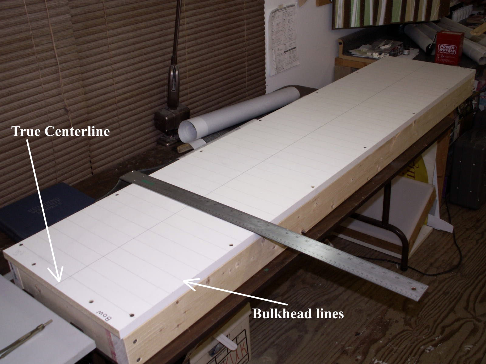
The critical item to remember is that your building board needs to be FLAT. I used a piece of the white melamine shelf board available at Lowe's or Home Depot, which I then screwed down to a frame made of 2X4 studs. If necessary you can shim the board to adjust for high and low spots as you check it with a good carpenter's level. When the board is done, and you have checked it thoroughly (make sure the edges are parallel to each other too) you need to strike a good centerline with a permanent marker and a true straight edge. The lines that run across the centerline are marked in pencil so they can be erased later on, and the board can be used for another project. These lines are for the locations of each of the cross-sectional bulkheads in the hull, and you can use a good drafting "T" square to mark them. I also recommend that you mark a line at the Bow and Stern to indicate the extreme length of the hull, and letterthem "Bow" and "Stern". I have gotten them confused before and managed to put my hull frame down on the board to glue things together, and then wondered why nothing would match up with my measurements. It sucks to go back and have to deconstruct your work for such a boneheaded mistake.
The next item to do is make your templates for the hull. First, use some poster board to make a profile view of the ship. You may need to tape several pieces of poster board together to have something long enough for the whole profile of the ship. A good way to do this is to tape down the poster board to your building board and use it as a drafting table. Draw a true baseline along the bottom of the page. This baseline is where all your measurements will be taken from. Next, use your "T" square to draw perpendicular lines at the extreme bow and stern lengths along the baseline. This establishes the ship's overall length. There is a personal trick of mine that I like to do; draw a line in red ink or pencil at the exact center of the ship, which I like to call the "CP" or center point of the model's length. The last thing to do is draw the perpendicular lines along the baseline that mark the locations of the bulkheads. Usually, there are about 40 bulkheads shown in the cross-sectional views for ships about this size, which is 600'.
The next item may be a bit of a pain depending on whether or not your plans include a complete profile view of the ship from stem to stern. If you do have a complete view then you are all set. Simply make a copy of the sheer plan at your local copy store, trim it to leave just a bit of paper outside the lines of the profile, and glue it to the poster board, making sure to line up the baselines and bulkhead lines perfectly. Now, carefully cut out your centerboard, or profile (the bulk head locations should be very clearly shown at all times).
If you are not that lucky, or the universe just hates you then you will have to do it the hard way. Once the baseline is struck on your poster board draw the bulkhead locations as previously described with your "T" square. Keep checking every single time you draw a line that you drew it in the correct place and distance, etc., and my personal recommendation is to always work in the same direction. If you start measuring and drawing your lines at the bow and work toward the stern, then make sure that you always repeat that process for every other step in laying out your model. It will help to make sure you never miss anything as you work, so get into the habit.
Once the bulkhead locations are drawn use your dividers to measure from the baseline up to the deck at each of the bulkhead locations, and mark the height. Now use your French curves to draw in the sheer line of the ship on the poster board. IMPORTANT NOTE HERE! Make sure that when you measure from the baseline to the deck you do so at the CENTERLINE. Most ships have "camber", or an arc in the deck, so the edge of the deck near the side of the ship is lower by several inches, or even as much as a foot, than the centerline measurement. You can get that information from a cross-sectional view. Of course, you only need to worry about it if you intend to put in the deck camber. Many modelers choose not to include it for radio-controlled ships. At any rate it makes a big difference when you cut the frames out later, try to add them to the keel and then notice that one item does not fit the other. Yes, I have done that too, and I can almost guarantee that when you try to draw in the sheer line with your French Curves it will not fit exactly.
The Sheer Line of a ship is generally graceful, and the profile views of most plans will show the Centerline Sheer and the Deck Edge Sheer. This is usually a representative of the camber I spoke of earlier. Make sure you are measuring the true Centerline Sheer to obtain the distances you need to draw the sheer onto your template. Then double-check that your measurements are correct. The main point is that you will notice some variances from bulkhead to bulkhead, and you should not fret about it too much. Just use your French Curves to make the sheer as graceful as you can, and compare your work to whatever photographs you have. If you intend to add the Deck Camber to your model then you can do so when you work on the Bulkheads. Once all this is finished you can cut out your profile.

If you are not ready to throw up your hands and walk away by now you probably will be by the time the next part is done. Again, if you have a really great set of well-drawn accurate plans for the bulkheads then you are set. Take your cross-sectional view to the copy shop and make as many copies of it as there are bulkheads, plus a few extra for mistakes. Cut your poster board into standard sized squares, and mark each with a true baseline and perpendicular centerline.
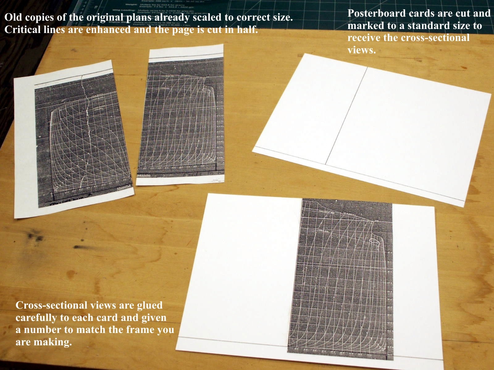
Cut each copy of the bulkheads apart at the vertical centerline, and trim the rest of the excess paper around the drawing so the remainder will fit on your poster board square, and glue it down so that the baselines and centerlines of everything line up perfectly. I like to use some kind of roller to make sure the copy is glued down evenly to the poster board. Write a number that will correspond to each bulkhead on one corner of the square that will become your template. Use a new hobby knife blade to first cut the square along the vertical centerline, and then cut out the bulkhead.

It is important that your cuts be as accurate as possible since this step will determine the shape of your hull. Keep both parts of all the templates. Believe me you will find them all useful.
Let's assume you had no trouble making your templates up to this point because your plans were of really good quality. If so, then now is the time to double-check your templates with your center profile template. If it all works out well then you are almost ready to cut out the centerboard and bulkheads. Incidentally, I like to use door skin plywood or aircraft grade plywood for the centerboard and bulkheads. Now you have a choice to make. If you are a purist, then you will want your model to match the actual ship perfectly in dimensions, and will want to draw the bulkheads on your preferred material with your templates, MINUS the thickness of your covering material, i.e. 1/8" X 1" balsa strip wood. The best way is to draw the shape of your bulkhead onto the board, and cut out the bulkhead. Then you can use a compass to trace a line around the bulkhead 1/8" from the edge, and remove that much more from the piece. In this case, I would personally use a drum or table sander to do the job. It offers more control when working with such small increments. If you don't care that much about this issue, then by all means, don't worry about it. The extra width may even be a benefit to the model by adding a minute amount of extra stability in the water. Once this issue is resolved you will need to remove some portion of the bulkhead in the middle to make the hull hollow. I like to use the compass to set a line 1" inside the outer edge of my bulkheads (you will do the same thing for the centerboard/ profile piece). You can leave the top of the bulkhead intact if you wish, to give yourself a basis for the deck, and for the sake of strength when you glue it to the keel/ centerboard, or you can cut it off and simply attach the former bulkhead, now called a "frame," only to the keel. There are a myriad of ways to do all this and they all work well. The point is to take your time and be accurate when you make your calculations and cuts. Try to look at the parts as you make each one, and imagine how it will fit together with the centerboard to form the hull framing before you even glue anything, and continually lay out everything to test the fit of all the parts. You will find that many times you can actually foresee problems and make corrections before they become problems. By the way, we are NOT gluing anything yet!
Let's say that the universe really does hate you, and all the plans of the ship you want to build are really bad. Again, you will have to do the layout and production of the bulkheads the hard way by re-drawing your templates. Case in point, the plans for the Langley were white line on black background, copied very poorly, and in many cases were almost unreadable.
This situation is extremely common, perhaps even normal. To correct the problem I had to follow the procedure already described, then take a couple of extra steps.
In some cases, a person could simply take plans like these, lay them on a light table to see lines that would otherwise be unclear, and trace the bulkhead onto some tracing paper. That only works once in a while. Most of the time you will not be able to clearly see the lines because of a smudge, or some other quality issue. At this point what you need to reach for is a good set of black line on white background drawings, which means you need to re-draw all the bulkheads the same way.
To start the process, first cut the squares of poster board as described above, draw in the baselines and vertical centerlines, and trim and glue the bad copies the same way as already described, but do not cut them apart at the vertical centerline. Number the cards for each of the bulkheads. Next lay out one good piece of poster board, and draw the baseline and vertical centerlines. Another good thing to do is draw in the other lift lines that are probably drawn on the original cross sectional views (these are all parallel to the baseline). Make sure you use the original measurements. These lines can also help make sure that any bulkhead lines you draw on this page will be symmetrical. This will eventually become your new master copy of the bulkheads. Go back to your bad copies and find the extreme widest point of the hull. Measure with some dividers from the Baseline up to the widest point of the hull on BOTH sides of the centerline. Draw a line with a straight edge across each of the copies. It helps to use another color of ink like red.
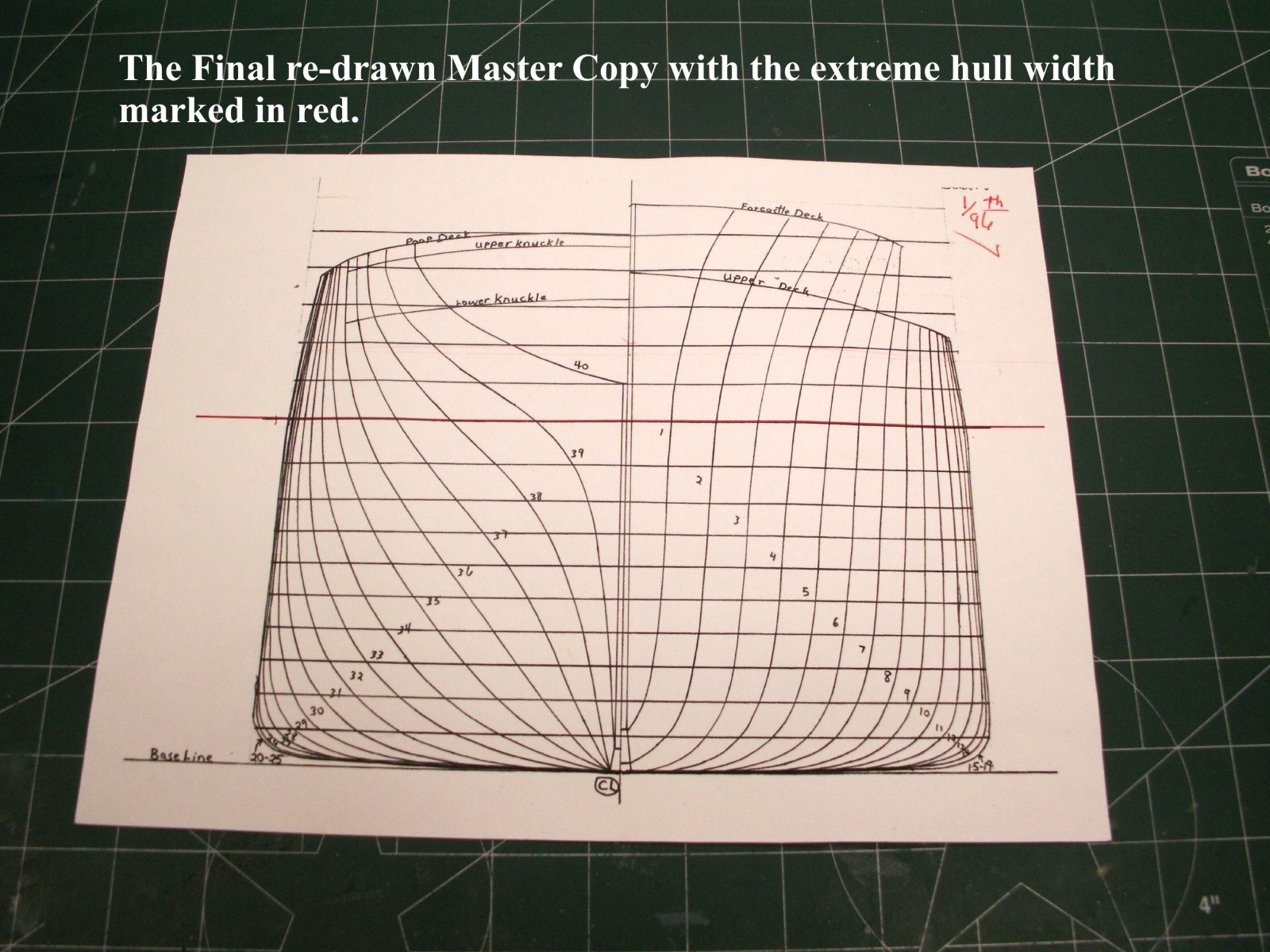
This line will help you later when you set the bulkhead on the keel. Since you have to draw your own bulkheads it will give you another reference point to use to keep everything true. Go back to your blank Master Copy page that you set aside, and draw the same line for the widest point of the hull on it.
Now the fun begins. Cut out the bulkhead templates from the poor copies as well as you can.

Frankly, in some cases you will have to guess if a line is just not clear enough to see. When you have cut out all the templates you can use them to draw new bulkheads onto the white background Master Page.
Why the extra step if you already have a set of templates? Well, the answer is that you may (probably) have made a mistake on one or more of the bulkheads in the cutting because the original copy was so bad. If you make a new set of bulkheads that are clear and clean, you will be able to see the mistake more clearly, and correct it. You are also less likely to make a mistake when you actually cut out the template because some clutter on the page confused you. Yes, I have done that too. You also have a set of good quality templates that act as a record of your work, and can be used to help you sort out any problems you encounter as you work.
Line up each template on the new Master Page starting with number one and draw in the shape of your bulkhead. The most important thing to remember is, TRUST YOUR REFFERENCE POINTS - the baseline, vertical centerline, and line showing the level at which the hull is at its widest point. In most cases you will notice that the bulkhead lines come closer together as they work outward toward the widest points of the hull until they simply disappear into one another. You should not have a problem as you lay in each line unless some lines cross over one another. In most cases, if there is a problem with your work it will be obvious and easily correctable if you draw the bulkheads with a light pencil. Just make sure you correct the problem immediately. If everything looks good you can then go back with a drafting pen and draw the same lines in black ink. When finished, go back to the copy store and copy, Baby, copy!!! After you have a good set of bulkhead copies in hand go back and glue them to a set of poster board squares as described earlier, and cut them out the same way.

Be sure to check your work often, take your time, and always use sharp hobby blades to cut out the templates.
Now that you have a great set of accurate templates for the profile and cross sectional views (bulkheads) you can begin drawing them onto your choice of plywood. First, draw a series of baselines and vertical centerlines on the plywood.
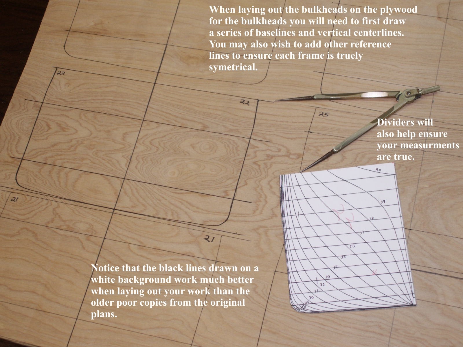
You need to transfer some of the primary reference points of each bulkhead onto the plywood to make sure each bulkhead is exactly the same as its matching template. This includes the line for the extreme width of the hull. You can add whatever other lines and reference points you wish, and it helps if you designate them with other colors of ink Notice that each of these primary lines extends beyond the dimensions of the template. This allows you to see that the template is placed properly on both sides of the vertical centerline. Even a slight offset or miscalculation in distance from any of the Primary Lines will result in a bulkhead that will totally throw off the shape of the hull, so be very accurate at this point. Lay each of your templates on the board, align your reference points, and carefully draw in the bulkhead. Flip the template over and repeat the process. Be sure to number the bulkhead with a bold marker. You should also draw the location of a notch on each bulkhead that is used to connect the bulkhead to the keel/ centerboard.
One trick I used when locating the frame templates on the plywood when laying them out. I used a sharp pointed "scribe" ( a hobby knife handle with a sharp meedle in it) to locate the frames precisely on the plywood. I laid the template in place, aligned it carefully, and used my scribe to push through the template into the wood at the points that I wanted to draw a line on both sides of the vertical centerline. When I lifted the template away from the wood I had a very precise pair of points that I could draw the line between.
In the case of the Langley I chose to use a keel built up from ¼" X 1" oak strip, and plywood pieces on each end.
The model is for radio control and needs to have a great deal of open area within the hull. If you are building a hull for static display you can simply cut out the centerboard from one piece of plywood, and cut a series of notches in all the bulkheads about half way up from the baseline that are as wide as the thickness of your plywood. Then you cut matching notches into the centerboard from the deck level at each bulkhead location that will match the appropriate bulkhead. The fit should be snug when the two pieces are put together like an insert for the liquor bottle crates you find in a liquor store. The bulkheads are then glued into place, notches are cut into the outer edges of the bulkheads to accept stringers, and the whole frame is then covered with strips of wood.
If your model is for radio control then you will basically do the same procedure above, except that the bulkheads will be cut on the inside of their dimensions, leaving enough wood at the bottom of each piece to accept a notch for the keel, thus turning them into frames. Each is notched to fit your keel snuggly. Once all the drawing is done you can cut out the bulkheads. A scroll saw is a wonderful tool to use as the primary means of rough cutting each piece. Keep clear of your lines with the saw, and use a disc sander or some other similar device to set the final shape of the bulkheads. Hand sand any roughness and splinters away. This takes a good while to do and is a bit monotonous, but it is absolutely critical to work accurately. Test fit each frame to the keel as you complete it. Make sure it sits squarely and snuggly on the keel.
At this point I should say a word on the actual assembly of the hull frame. As you read many articles and opinions on the subject you will find that some people like to leave an extra area of wood attached to the top of each frame. They then attach the frames to the building board upside down, and insert the keel or centerboard into the notches and build the hull upside down. Later they cut off the excess portion of the frames and clean up the sheer line that is now right side up. This is a nice practice and has many advantages, the best perhaps being that it will prevent the hull framing from twisting like a corkscrew as you work on it. Other people build the hull right side up, as I did for the Langley. There are as many opinions about how to assemble the hull as there are people building models, and all are valid if they work. You should proceed with whatever method you are most comfortable with, and by all means, experiment with new ideas and tips from those more experienced than you. Regardless of the assembly method make sure that whatever you do on one side, you repeat for the other so that all torsional stresses are equalized at all times. The biggest problem with framed up models is twisting.
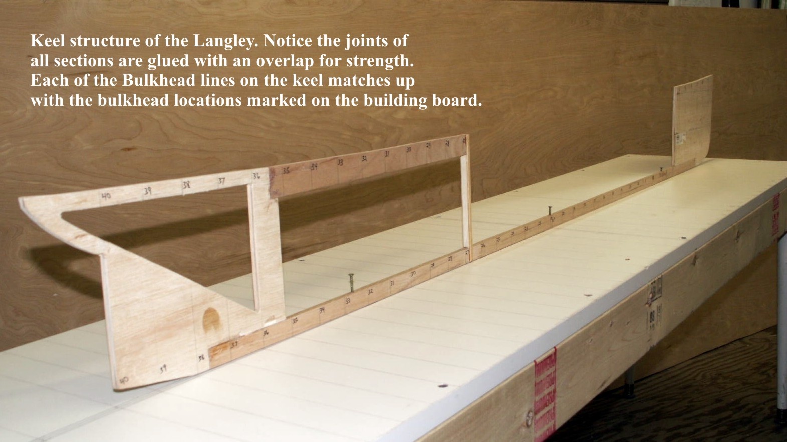
Once all the hull frames and keel parts are cut out, cleaned up, test fitted, and marked/ corrected as appropriate you may now begin the actual assembly of the hull frame. In the case of the Langley I glued a series of wood blocks at intervals along both sides of the building board centerline that would firmly hold the keel in a perfectly straight line, but would not interfere with the frame locations along the keel.

Next I drilled three holes in the keel that passed all the way through the building board at roughly equal points that were big enough to accept a nail. The nails were pressed through the keel and into the building board to hold the entire keel and frame to the board, and help prevent any movement.

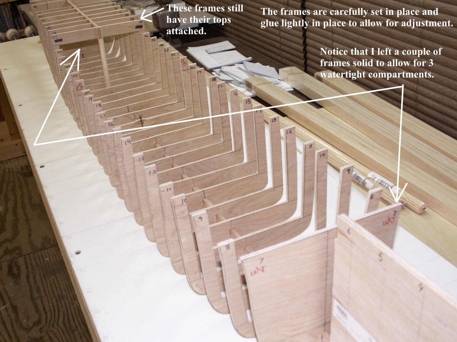
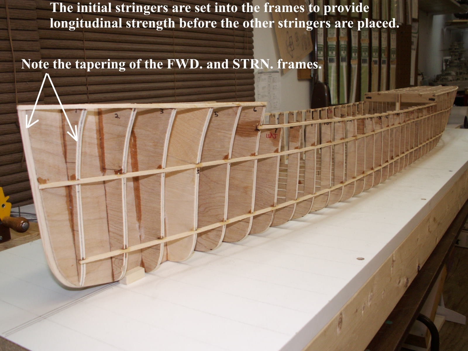
With the keel in place I began setting the frames in place and fixing them with only a spot of glue that would allow me to make minor adjustments later. I used a waterline marker to make sure each frame was set exactly the same height on both sides as I attached them to the keel. I also used a drafting triangle to ensure that each frame was perfectly square to the keel, and to the baseboard, i.e. truly vertical, as I worked down the length of the hull. You may notice that the frames at the bow are solid.

This is to increase strength at the bow, which is typically a weak point on functional model ships. You may also notice that the frames near the stern have the tops attached. This was done to make sure that this area of the ship had a solid base upon which to build the poop deck structures. I also left several frames in their solid form to create 3 watertight compartments in the hull. This was done to simply help prevent disaster on the pond.
When all the frames were attached to the keel, and checked, I attached balsa blocks to the rounded stern to provide a solid filler to attach planking to, and to reinforce the joints of the frames in that area. This is done at the bow as well.

I also calculated the size of the rudder shaft exit tube, and drilled an appropriate hole in the keel. This provision allowed me to ensure there would be plenty of room for the rudder servo and pushrods to remain clear of obstruction before I covered the hull. Had there been any problems it would have been much easier to figure out how to fix it.
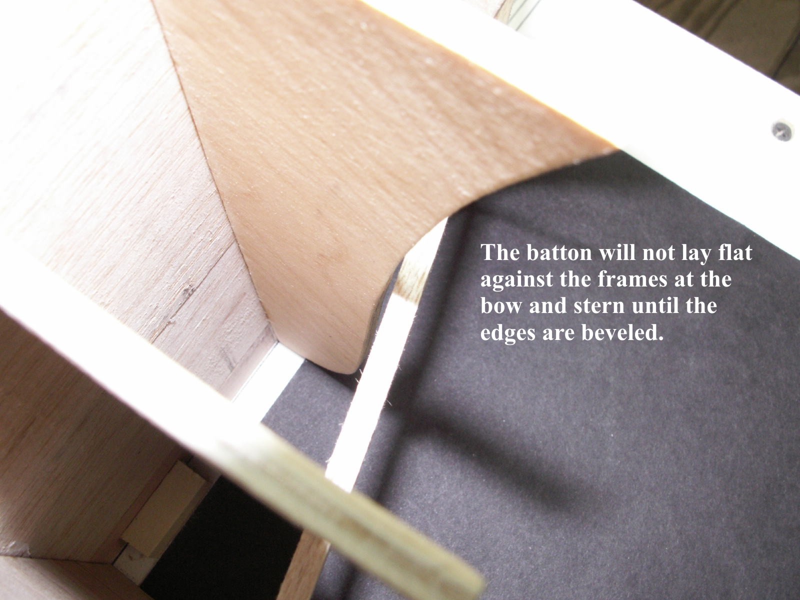
Before any other attachments to the frames can be made, such as stringers that run lengthwise along the frames, some adjustment needs to be made to the frames to ensure a smooth contour of the final product. If you clamp a straight strip of spruce approximately 1/8" X 3/16" X 36" (called a batten) to the frames you can see exactly how true your work is by observing where it touches the frames.

In some areas along its length it may not touch a particular frame at all. In that case you will need to glue a strip of wood to the outer edge of the frame to take up the space in between the frame and that batten.

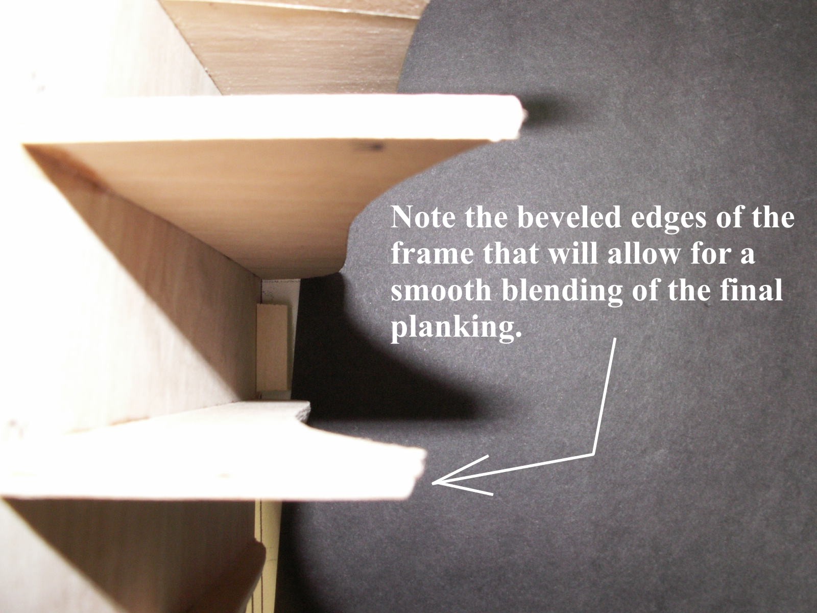
In other cases you may be able to see that a particular frame sticks out farther than the others. It will have to be sanded down to the same level. Frames at the bow and stern will not allow the batten to lie flat on their edges until they are sanded at an angle matching the curvature of the hull.
The battens should be used liberally along many different areas of the structure to ensure that all frames are touching at the same level, and to ensure that the hull has a graceful shape that follows what is seen in pictures. The more time you spend faring the frames, the less time you will spend sanding the planked hull - time spent at this step if very worthwhile.
The hull frame now needs to have support lengthwise, and that support comes from "stringers." These stringers are merely 1/8" square strips of spruce wood that are glued into notches cut into the edges of the frames. The best tool I have found to do the job is a Dremel Tool with a 90-degree angle attachment, and a fiber-cutting disc. To make your cuts, first set your waterline marker to a depth about halfway up the side of the hull near the center point of its length. Mark that location with a pencil, and move the waterline marker along the hull marking each frame as you go. Repeat the process on the other side, and start cutting 1/8" notches at each mark. Insert the strip as you work down the hull, and make sure the strip has a nice straight run all the way along its length. Repeat on the other side, and glue the strips into place. Next apply the same technique to add strips along the tops of the frames to create the sheer line of the hull on both sides.
It is important to make this as smooth and graceful as possible. A bar sander of the type that many R/C Model Airplane hobbyists use to build their models is perfect for this. These early sets of stringers will help keep the model's shape true while you continue adding more stringers. One important thing to remember is that all the stringers should follow the natural curve of the hull shape. Don't try to force them to take a certain shape or follow a certain course along the hull.
Forcing the stringers will only add twisting stresses to the hull that could cause it to distort. Once the stringers are all in place use your sanding bar to smooth out the hull. When you lay a strip of 1"X 1/8" balsa strip on the frame, the same way you did for the batten, it should lie flat against the frame and stringer surfaces. You may need to glue strips of wood onto the framing surfaces in any low spots you find, or sand down high spots you see as you sight down the length of the hull.
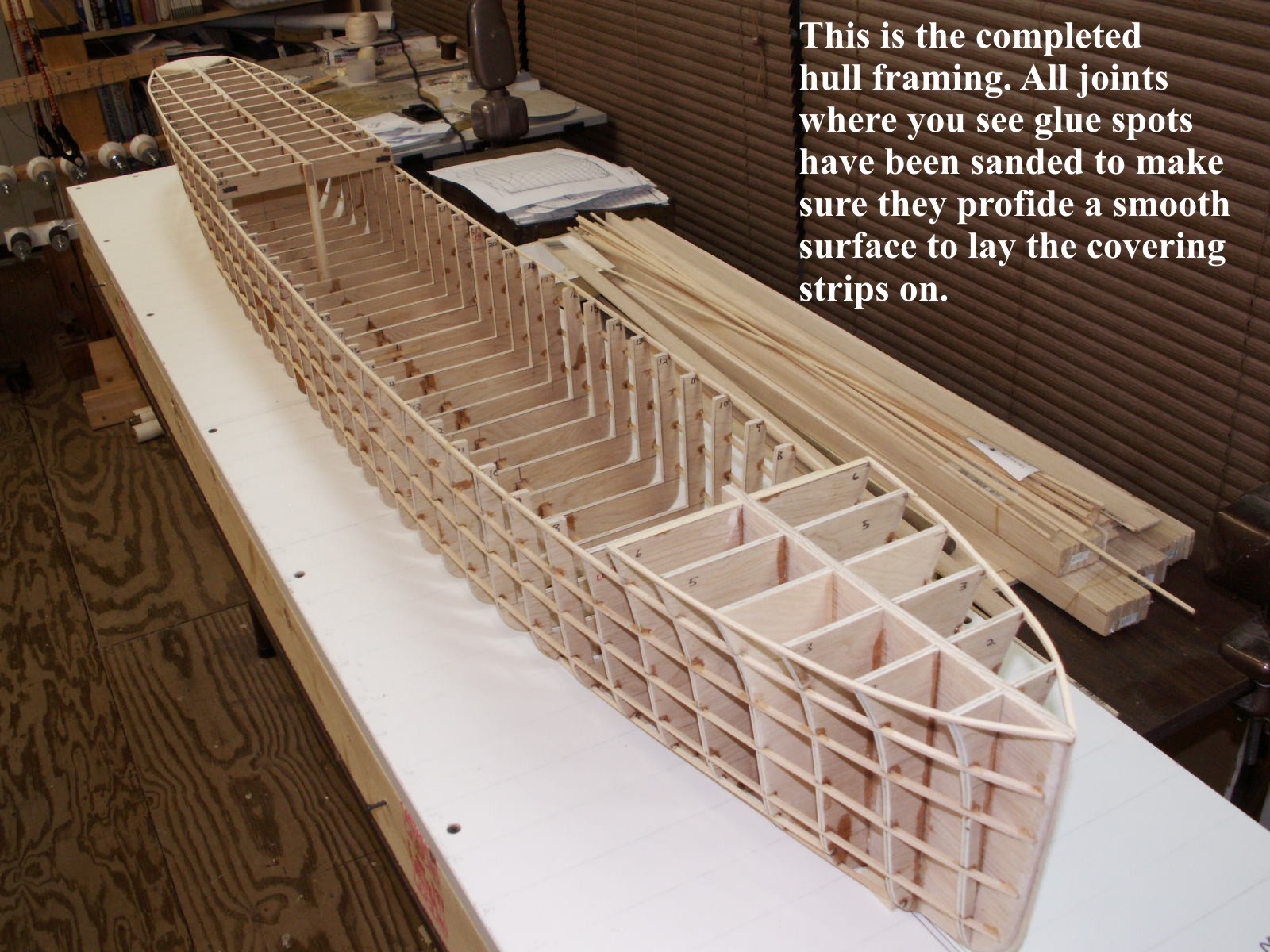
By now you may think the universe hates you a little less, or maybe you just know what you are doing by now. Either way the primary hull framing is done and it is time to start putting on the covering. In this case 1"X1/8"X36" balsa strips are what I used on the Langley. Basswood can also be used if additional strength is required.
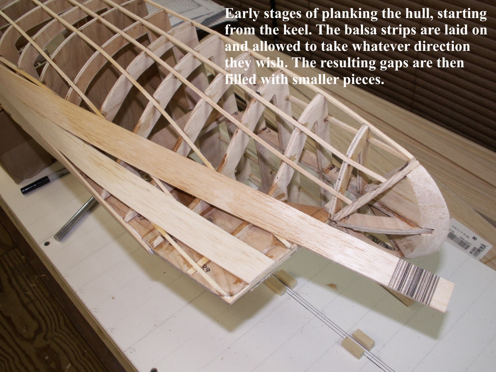
I will emphasise again, when you attach one plank on one side, be sure to do the exact same thing on the other side to prevent twisting. My personal preference is to start planking the hull on the bottom, and working upward toward the top. Once I reach the lower part of the framing that starts to curve upward I move to the side of the ship, and continue up the side to the deck level. Excess is cut and sanded off. Then I go back to the gap left between the bottom and sides, and fill it in with smaller, more controllable strips of balsa. The key is to follow the same direction given earlier; and don't try to force the wood to take an unnatural curve; let it follow whatever shape it wants to take, and fill in any gaps with smaller pieces later. It also helps to keep a plastic planting trough filled with water on hand to soak the balsa wood strips in, since wet balsa will bend around the various curves of the hull much easier than dry wood. The final appearance of the covering is unimportant. What is important is that the planks are all applied tightly against one another, and that the hull has no dips, bumps, or irregularities in its surface.
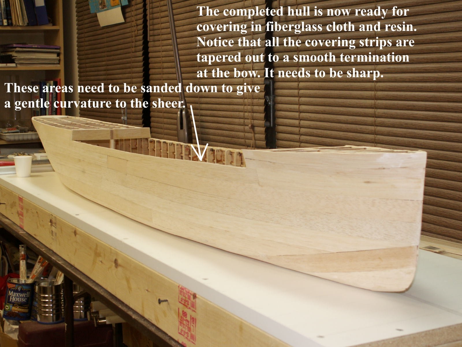
If you find any of these problems you can fill them in with auto body or balsa putty, and smooth it out. You can also glue another layer of wood on top of the first layer and sand it. After the hull is smooth and true you will need to apply a couple of layers of ¼ oz. fiberglass cloth and resin to the surface. The best way to do this is to apply the first layer of cloth and resin using a disposable paint roller, and let it dry completely. Repeat the process for the second layer of fiberglass resin and cloth, but make the resin layer a bit heavier. When it has dried sand the hull until you have a nice smooth surface, but do not sand so much that you go all the way through the fiberglass and back into the wood. If you think it is becoming too thin use a bit of auto body putty to fill in the area. When you think you have finished the sanding go over the entire surface and note any pinholes and other little problems. Apply putty to those areas and smooth out when dry. A light coat of auto primer spray paint will reveal anything else you missed. Drill out the propeller shaft exits and strut locations, and install them now so you will be able to ensure they are neatly cleaned up and blended with your hull.
Although the Langley hull didn't have this, a lot of warhips have distinctive "knuckle" in a hull. In order that it be very noticable in the final product, I will carefully mark the frame with my waterline marker after all the stringers are placed in the hull frame, and then cut a very precise set of slots at those points wherever the knuckle is supposed to show. I then glue in a very thin strip of dark hardwood, such as walnut that is also left standing proud of the final blasa planking. The hardwood is then sanded down to the surface of the planking and you are left with a wonderful obvious locator for the knuckle, that is also tougher than the balsa, and therefore, will retain the sharp angles you want to impart in the hull.
After the hull is built, covered and smoothed you can add details like bilge keels, plating, rivets, hawse lips, and other items that should be permanently attached. At this point you will be adding the sub-decks and all supporting structures before you move on to the real work on the model, the superstructure.
I leave off here because if you have mastered your model to this point you do not need any further hand holding from me. I truly hope this article is helpful to those who have felt the desire to build a hull, but always questioned their ability to actually do it. Remember that every ship model builder has been a novice. We all understand how it feels to be daunted by the confusing lines and marks on a page of plans. However, if you just jump in and try it, understand that you will make mistakes, and take the time to think out the entire process before you attempt it, you will be rewarded with a positive outcome of your work, and find you have a whole new host of skills to be proud of.
William Blackmore is owner of Cottage Industry Models, a manufacturer of resin Civil War era ship and gun emplacement kits.

Back to Construction Articles
2585 vists so far.
Version 1.0
10/08
![]()