(Click on any photo to see a larger version)
When building a scale model ship, access to rudders can be a problem if scale appearance is desired. The usual way is to have a removable access hatch in the deck, and to try and disguise this as well as you can. With the helicopter deck on my model destroyer, the USS John Paul Jones (DDG-53), I knew I wasn't going to be happy with this approach, so years ago I began working on alternatives that would allow me to drop the rudders for service and propeller access while maintaining scale appearance.
The first solution was to use long aluminum tubes with brass shafts inside them that terminated just before the rudder post inside the model. Small hex wrenches were soldered into the brass shaft and they could be pushed into place from the engine compartment of the model to hold the tiller in place and loosen the hex screw. The system work fairly well, but the hex key and set screw were susceptible to corrosion, and you had to be careful not to jostle the model while the rudder was out, less the tiller fall off the hex screw.
As the years went by, my friend Dave Manley came up with a way to retain a rudder using a snap clip and ball on the top, soldering into square hollow tubing that would engage a tiller. This was a big step in the right direction, and for a couple of years a few of us experimented with different variations of the same design, mostly using a retaining fork that could be slid in and out of position from inside the model, much like the original hex wrench / shaft design. This is the system currently in use on my battleship Gneisenau and it works, but it requires care in the set up or binding and other problems will result.
Last winter, I was on the phone with Lee Upshaw of the Scale Shipyard, and we were talking about various uses for rare earth magnets, including the linkage connectors that Dave Merriman had come up with - they used small diameter rod magnets to provide a positive, yet easily disconnected connection for small scale model subs. While we were talking it occurred to me that this sort of system could be used to retain model rudders.
The first installation went into Lee's Graf Spee in December, and it appears to be working fine, but was still too complicated. After some further thought, I came up with the system described in this article. It can be built with the tools most large scale modelers have on hand - no lathe or mill is required, thought they do make a couple of the operation much quicker, as I will detail further in a few paragraphs.
(Click on any photo to see a larger version)
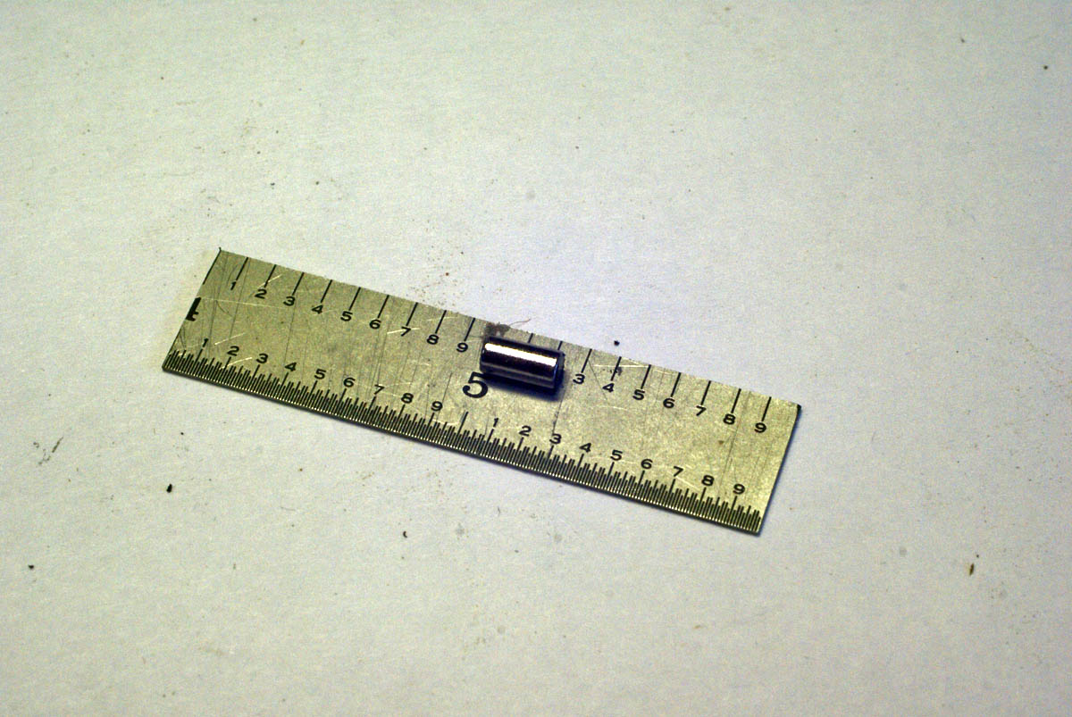
The heart of the system are rod-shaped rare earth magnets. I got mine from KJ Magnetics - you need a size that will fit into K & S hollow square tubing. For the John Paul Jones, 1/8" X 3/8" turned out to be perfect.
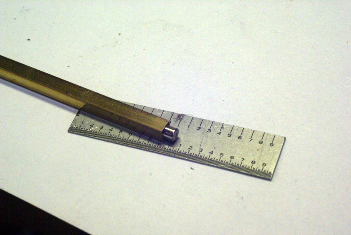
Since this was a retrofit to an existing model, I needed to cut the existing rudder shaft down, slip a piece of square tubing over it, and a a piece of round tubing over that to serve as the bearing surface. Luckily, the Burke class destroyers have fairly large diameter rudder shafts so even after that I maintained the scale footprint of the rudder post.
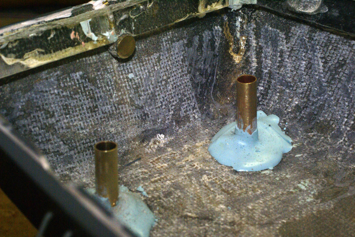
Since the rudder posts are larger than previous, I had to remove the existing tubes and replace them. To strengthen them I took a # 10 brass washer, bored it out slightly to fit the rudder tube, and soldered it onto the tube. I then tacked them into place using Cyanoacrylate (CA or superglue). I have had good luck with the Zap brand and use it in critical applications. Once the alignment was right I mixed up a batch of Evercoat catalyzing body putty and bedded the tubes into place. (Wonderful stuff, Evercoat, if you havne't seen my page on it be sure to check it out sometime.)
Once the rudder posts had been installed, I test fitted the rudder and trimmed it down to size so that it would be 3/8" higher than the rudder post.. In retrospect I should have waited to install the magnet until after I trimmed the piece, as it was quite tough to cut through even with a emery disc in a Dremel tool. I cut it very slowly, as overheating can damage rare earth magnets. It would have been much easier to glue the magnet in after this step - live and learn!
Because I have a lathe and mill, I made the tiller bodies out of solid brass and milled the slot into them on a mill. You could sleeve together brass tube instead, and either mill a slot with a Dremel or solder your tiller arms onto the bottom of the sleeve.
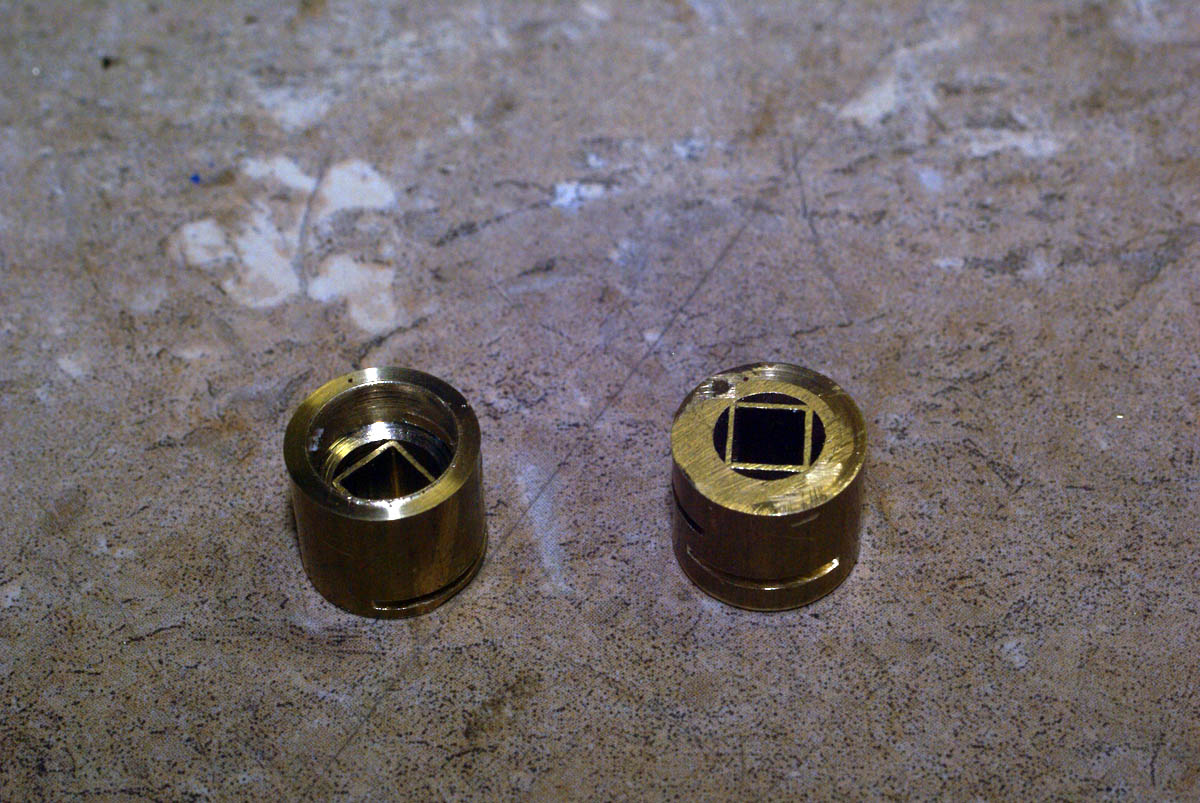
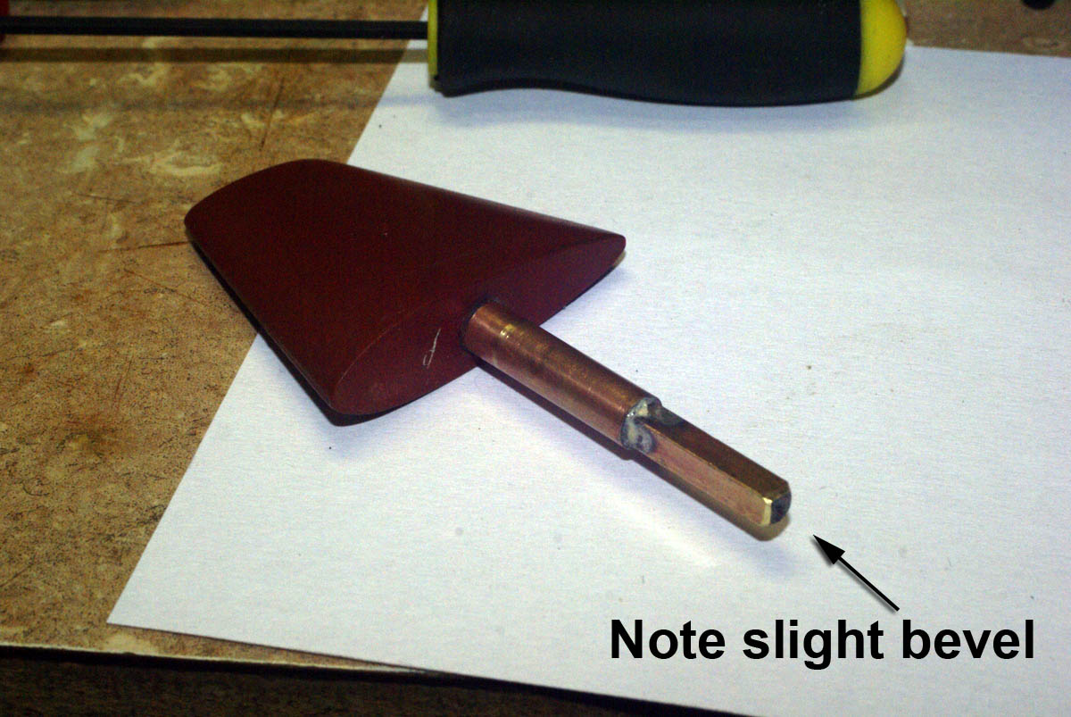
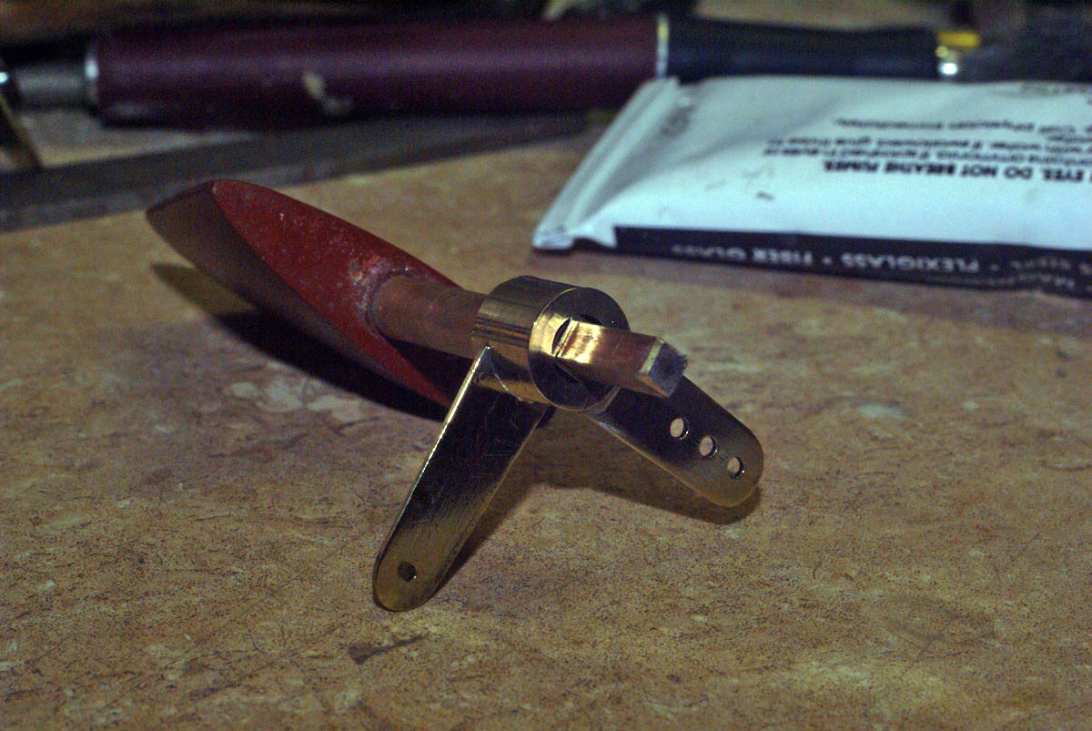
I bored a 1/4" hole through a piece of 7/16 brass, and then flipped it around and counter bored 3/8" about 1/8" deep. The counter bore allows the tiller arm to not bind on the rudder post when the rudder is assembled, and prevents the tiller from slipping off the post. The photograph above shows the top of one tiller body and the bottom of the other. The 1/4" bore allows for a nice tap fit of the square tubing, which orients the rudder to the tiller. No setscrew will be needed.
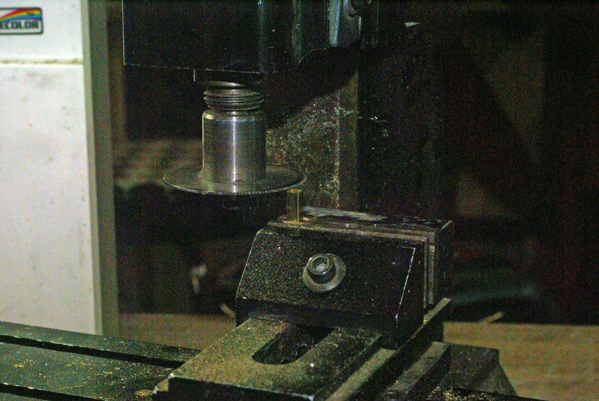
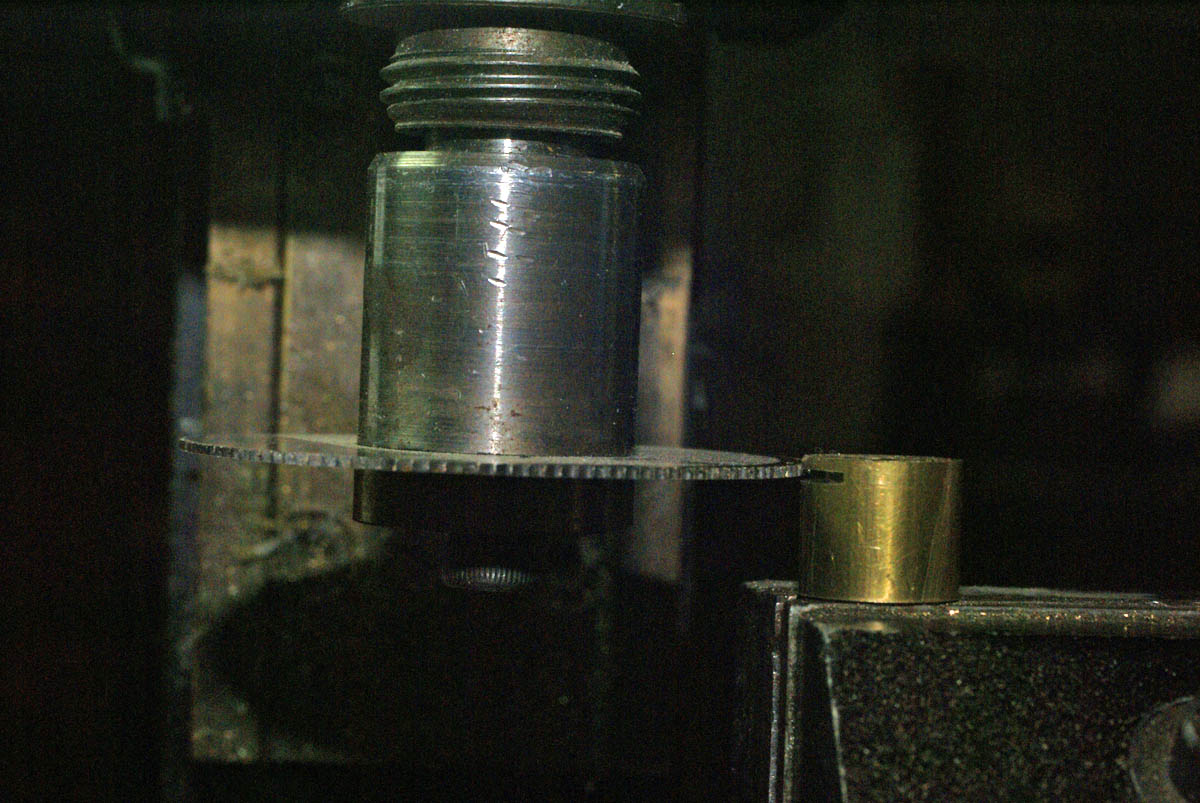
To cut the slot that will receive the tiller arm I used a .032 slotting blade mounting in my Sherline mill. I clamped a small length of square brass tubing into the milling vise, and this held the tiller body in place, and allowed for easy indexing of the second cut on the primary tiller, which needs two arms.; simply lift it off, rotate 90 degrees and slip it back on. Milling three slots took less than two minutes.
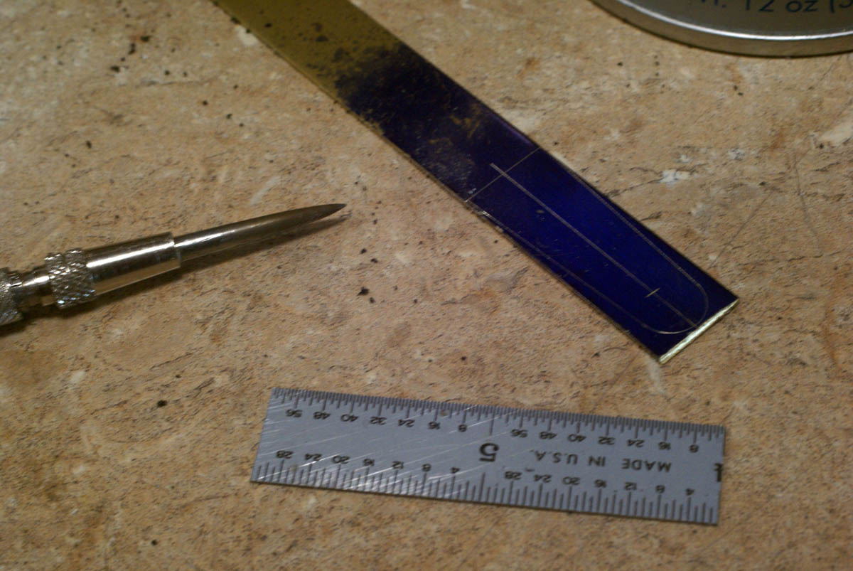
To mark out the tiller arms, I first sprayed .032 brass strip (another K & S product) with spray Dykem steel blue (here is one source, but shop around). I used to use the layout fluid that came in a brush top jar, but I find the spray dries faster and more evenly. By using a heat gun, you can be ready to scribe the lines in less than a minute.
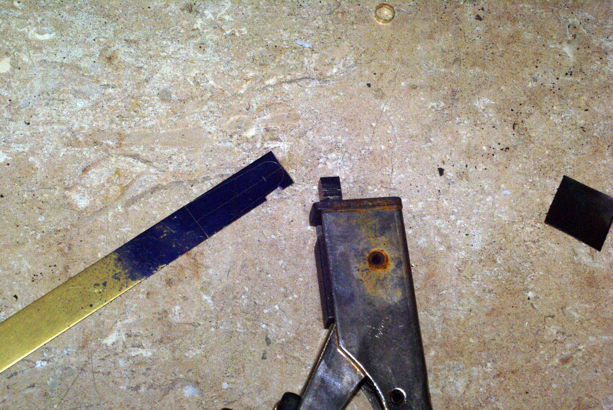
After marking the arms, and boring the holes to receive ball links, I cut them out of the brass sheet using a pretty low-tech nibbler from Radio Shack. For thin sheet metal, this is a great tool. After cutting them out I dressed the edges with files and a rotary tool.
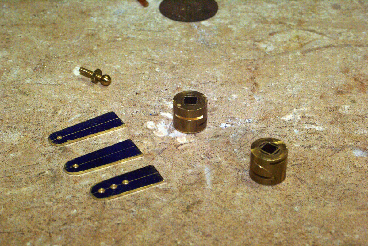
The finished components, ready to solder together, except for the ball which is installed later.
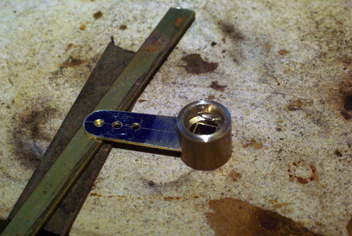
Because the slot was precise, it was very easy to tiller arm together. Because it was getting late at night, I had to do it a few times, as I installed the wrong arm on the wrong tiller. There is a moral in there somewhere... Note the use of brass sheet to support the end of the arm, in case heat expansion alters the fit.
My setup for soldering includes a ceramic soldering plate from a jewelry supply house, Staybrite solder, liquid flux, and an incredibly cheap (in every sense of the word) torch from Harbor Freight. Because of it's tendency to spit out random gusts of flame I cannot really recommend it, but it's lack of child safety locks actually make this feature less annoying than dealing with the better quality models currently available that require circus training to operate.
I flowed a bit of solder inside first to lock down the square tube.
And then fastened the arms on one at a time. Again the good fit made it much easier. If you do have an issue with the arm being too loose,. try taking a punch and put a few punch marks where the arm meets the body. The brass will swell around the area, tightening the fit. Ideally you should have a light tap fit.
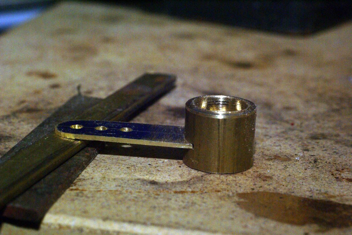
The soldered port tiller arm after a quick cleaning and polish. I use buffing wheels from Widget supply for the initial cleaning, and some Blue magic metal polish for the final, unnecessary shine. After all, this will be hidden inside the model, hopefully for many years.
Test fit of the tiller arm assembly on the rudder shaft. You want a nice smooth fit with no binding or slop.
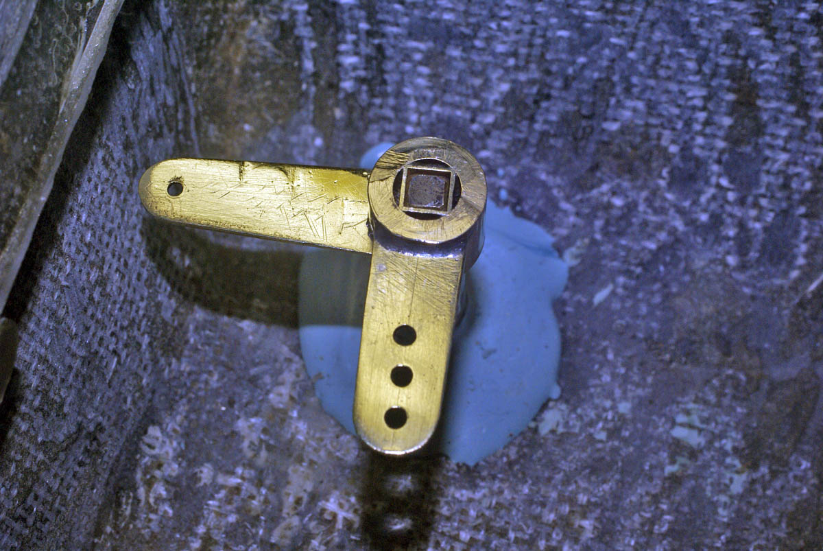
First test fit in the model, checking to make sure it rotates freely and doesn't hit the hull. Since this was a retrofit I used the existing equipment as a template for the tiller arm length and geometry, but if it was new I would mock it up using index card first.
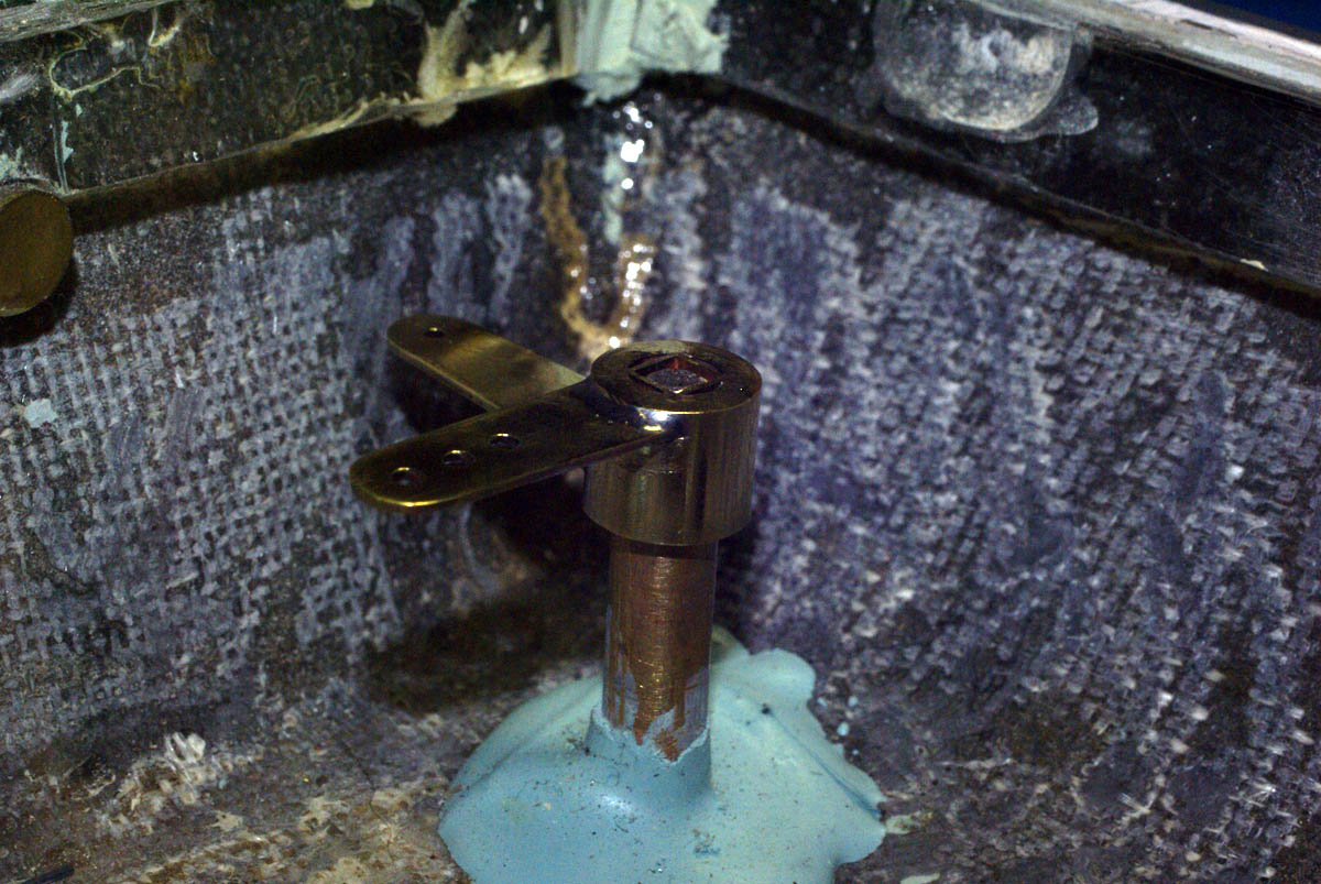
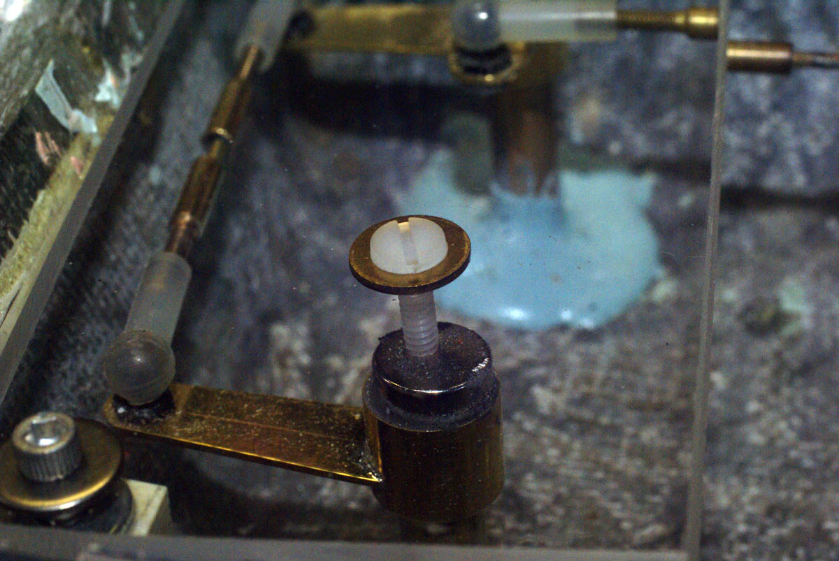
Testing the magnet's power. I thought it was going to take a larger magnet that ultimately needed to hold the rudder in place. In fact, even the small magnet that I ended up using was a bit overkill, as you will see from the video.
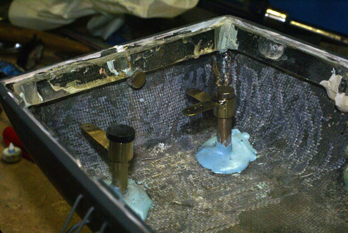
Both rudders temporarily held in place. I measure the distance between the two arms and built a ball linkage out of Dubro ball links, available from the local hobby shop or online.
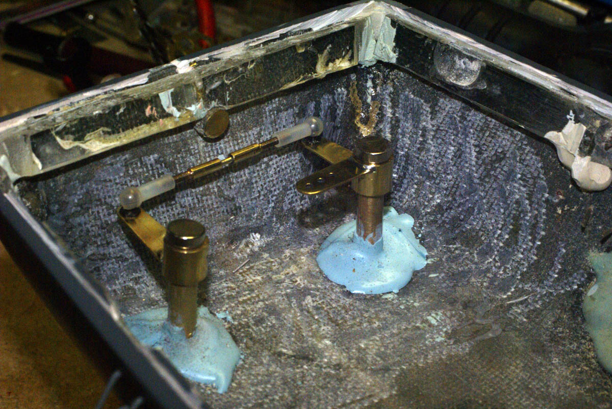
The connector linkage in place. The ball links are the best choice because the nylon connection eliminates a source of radio interference, the have no slop, and can accommodate slight misalignment.
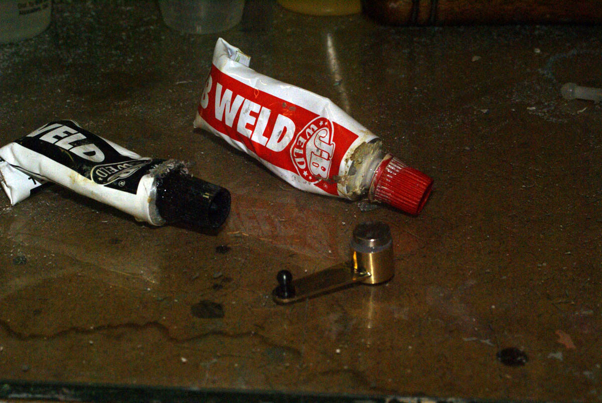
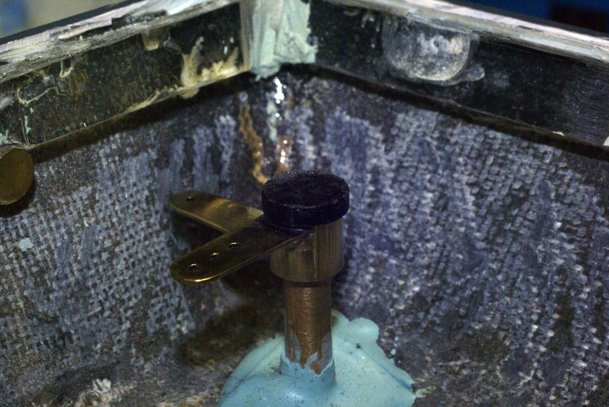
I glued the magnets to the top of the tiller assemblies with J-B weld. I have been using this product more and more as it is very tough - in fact, it solved a chronic cracking problem I had where two pieces of deck met at the bow of the Gneisenau. It's messy, smells bad, and works great. To aid in adhesion I scuffed both the top of the tiller assemblies and the bottom of the magnets with 80 grit sandpaper, and was careful not to get the adhesive down into the tube. When the adhesive ran into the tube anyway, I used a dental pick to clean it up.
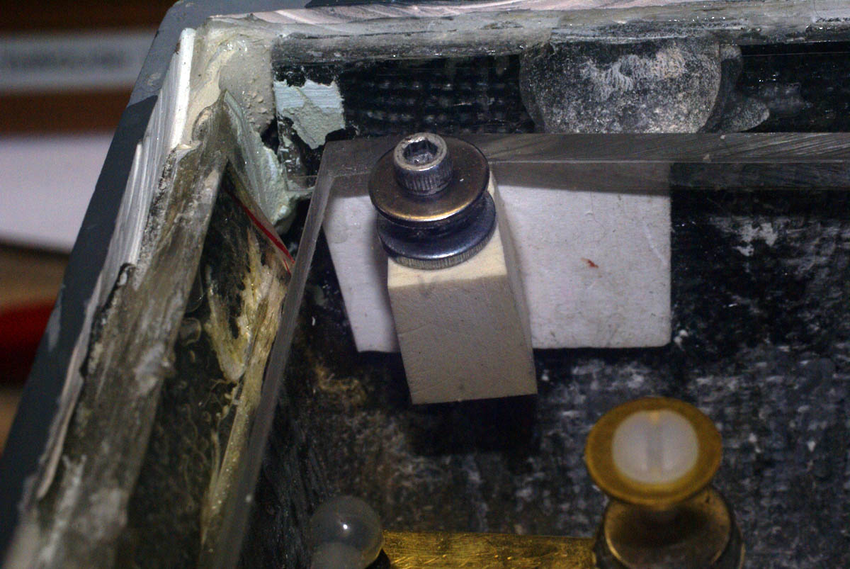
I glued small blocks of Butterboard into the corners to add as rudder stops and the foundation for the top plate. Rudder stops prevent your rudder from "flipping" if you hit something or have a glitch with your rudder servo. A rudder with a long linkage can spring into a position that renders it uncontrollable, locking the servo and generally ruining your day if it happens when you are running in formation with other models. These simple stops prevent that and are installed so they hit when the rudder is at 45 degrees, which is 10 degrees farther over than normal.
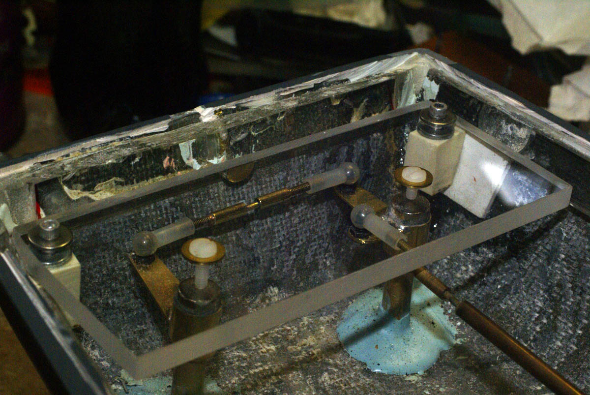
The final part is just a little insurance against the tillers popping off when you insert the rudder. A plexiglass plate is attached to the rudder stops, and two nylon (could be brass, just make sure non- magnetic) screws a run down so there is a slight gap between the top of the magnet and the bottom of the screw. The plate is made removable in case the assembly ever needs to be serviced, which I really hope will not happen.
Here is a video of one of the rudders being removed and reinserted. (2.63 Mb Quicktime movie;
If you have any questions, you can contact me through my message board.

For more Construction Articles click here.
125 visits so far.
Version 1.0
5/11
![]()