
Do you need the source code for this system? Click Here
Need a schematic diagram for the PC board? Click here.
Scale RC ship modelling is probably the most versatile form of modelling. It covers information research, planning, drafting, designing, actual building, many technical aspects, and of course operating the ships, preferably in groups.
One wants his ship not only to look like the real thing, it should also behave in the same way.
As we build warships, the first item in which we can add functionality is the control of the (main) gun battery. I've seen articles on the control of a single gun, and some on more or less complicated set-ups to train all guns of a battleship broadside. Some 20 years ago, I used small motors with reduction gears, belts, pulleys and micro-switches in my 1/200th BISMARCK. This then allowed the guns to either be centerline,broadside port or starboard.
Now, I am looking for something more.
My aim was to develop a system that would act as realistic as possible, while remaining simple in design and construction. When your ship is out there, in hostile waters, you want it to be reliable and simple to control.
I have developed this GFCS for my 1/48th scale DD449 USS NICHOLAS but, as you will see further on, it is usable on any type of ship, and in pretty much any scale.
Real GFCS work basically as follows.
A gun director is used to track the target that is to be engaged. Once a target is tracked, the measured data is fed into a calculator (in the NICHOLAS' days an analog computer) along with own ship data and ballistic properties of the controlled guns. The computer then calculates a predicted hitting point in which the fired projectile and the target will "meet". Control signals then pointed the turrets so that they fired at that calculated point.
I wanted the same overall functionality. First, have free control over the gun director from the transmitter. And be able to assign (or slave) the guns to the director
So I came up with following Operating Modes:

OFF: All turrets and the Mk37 gun director are steered to their centerline position.
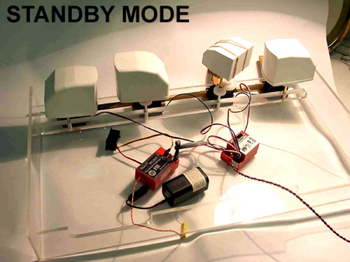
STANDBY: The Mk37 is under control of the RC system. The gun turrets remain in their last controlled position (either centerline if the previous mode was OFF, or at a set bearing if the previous mode was ASSIGNED)
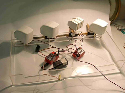
ASSIGNED: The turrets align with the Mk37 director.
In addition, I wanted the turrets and director to rotate in a realistic way. That is not as fast as modern servos can go. I also wanted to use all my guns, considering each gun's training limits. Elevating the guns was not essential.
I will of course use standard RC equipment. As two major controls can be discerned, I need to use two channels.
1. One to set the mode of operation (OFF, STANDBY or ASSIGNED). I will use a 3-position switch for this purpose.
2. And another channel to train the gun director. The left-right motion of the left stick will be reserved for this control.
To actually rotate the director and guns, I use Parallax 180DEG servos and a single-step 3/2 reduction gear. This allows for a turret or director to rotate over 270 degrees.
Note that the servos are true proportional types, and not the special 180DEG servos as used for landing gear control in RC aircraft. I have full proportional control over the full range from -135DEG to +135DEG.
Basically a box that goes between the RC receiver and the servos. This box should be able to interpret the RC signals, and generate appropriate pulses to control the servos. It even required some intelligence to achieve the desired GFCS functionality. To me it was obvious that a "computer" would be best suited to fulfil these tasks. There are a lot of controllers on the market, but I liked the "simplicity" of the Basic Stamp (from now on referred to as BS). There is also a lot if information available on the net. Even the editor/development system, that is the PC-software required to program the BS, and the Programming Manual can be downloaded.
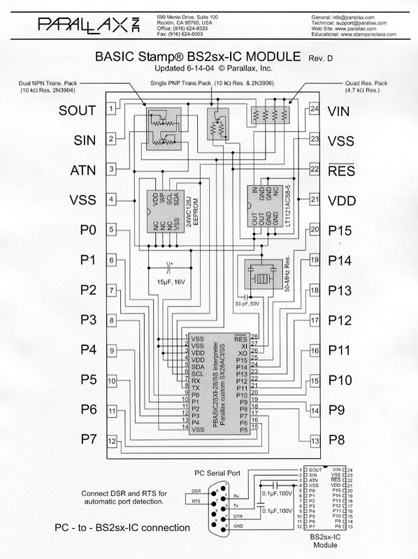
The BS is a micro controller. It comes in several types and configurations (see http://www.parallax.com ). I chose to use the SX type. This comes in the format of a 24 pin Integrated circuit as depicted below. Below is a description of the connections. (Both pictures come from the Parallax Basic Stamp Programming Manual).
Click to expand

Click to expand
Now would you believe that this is actually the only hardware that is required. You need of course a small PCB (Printed Circuit Board) to put the BS and the servo connectors on. But because of the (extremely) simple wiring, an experiment board can be used.
Click to expand
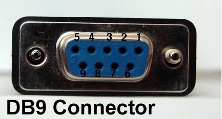
Some wiring to a DB9 female connector is also required so that you can connect the BS to a serial port on your PC during program development and debugging, and to load the BS with its program.
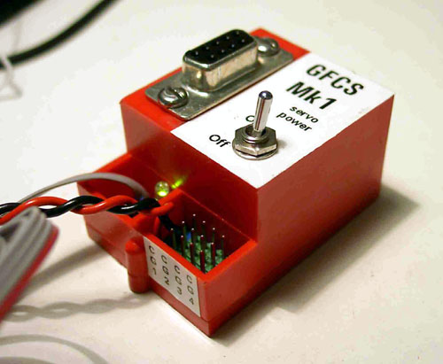
An overall view of the GFCS Mk1 with the DB9F connector for programming and the servo power switch on top. (This servo-power switch is very useful during development as you can shut the servos down before any damage is done. If for instance a too short or too long pulse is send, the servo strains against its mechanical stop). At the bottom are from left to right:
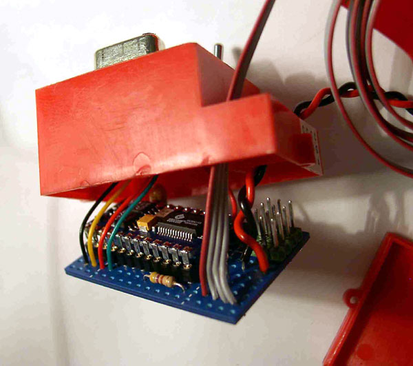
The Basic Stamp sits on an IC socket so that it can easily be removed. The series resistor is very visible in the front.
This is how I wired my GFCS. The table gives an overview of the connections made to the BS socket.
| Pin | Name | Connects to | Function |
| 1 | SOUT | DB9F 2 RX | For communication from BS to PC. |
| 2 | SIN | DB9F 3 TX | For communication from PC to BS. |
| 3 | ATN | DB9F 4 DTR | Control signal for communication. |
| 4 | VSS | DB9F 5 GND | To connect the ground signals of both systems. |
| DB9F 6 DSR DB9F 7 RTS |
These two sockets on the DB9F connecter must be connected for the PC software to work. | ||
| 5 | P0 | Director Servo | Servo pulse to servo on the Mk37 director |
| 6 | P1 | Guns #1 & #2 servo | Servo pulse to servo on Guns #1 & #2 |
| 7 | P2 | Gun #3 servo | Servo pulse to servo on Gun #3 |
| 8 | P3 | Guns #4 & #5 servo | Servo pulse to servo on Guns #4 & #5 |
| 12 | P7 | Status LED | LED is connected in series with a 330 OHM resistor to the VDD (receiver power). |
| 19 | P14 | RC Ch. "Mode" | GFCS Input of mode command from the receiver |
| 20 | P15 | RC Ch. "Bearing" | GFCS Input of bearing value from the receiver |
| 21 | VDD | + Power Receiver | Is the power supply connection for the Basic Stamp |
| 23 | VSS | - Power Receiver - Servo Power |
All - voltage or "ground" lines must be connected: PC, receiver power and separate servo power. |
All other pins are not connected. As you can see, there are plenty spare I/O pins to expand for future needs.
I use a separate 6V power supply to power the servos, controlled by the GFCS. This in order to reduce the load on the receiver battery.
To write a program, you simply must connect the BS with a standard serial cable to a free serial port on the PC and power it up. When you start the editor, it will detect on what port the BS is connected, and what type it is.
First, I planned a system with a separate control for each gun and the Mk37
(See Timing constraints below) but finally I came up with 4 control groups
(CG). These are the 4 separate controls that can be discerned for my 5-gun
destroyer.
In order to understand the software, some terms and functionalities are defined:
Servo Pulse.
A servo is an electronic device housing a small motor that, through a reduction gear, aligns an output shaft. A pulse that varies in length between 1ms and 2ms controls it. If the pulse is 1ms, the output shaft is in one extreme position, 2ms gives the opposite extreme position, and indeed 1.5ms set she servo to its centre position. The pulses have to be repeated app. every 20ms.
GFCS Pulse.
In order to control the Parallax 180 deg servos over their full range, a pulse length with a greater range is to be used. The GFCS performs the required conversions.
Current Position versus Desired Position.
I have these two values for each control group. The Current Position is actually a value representing the pulse length that is applied to the concerned servo (Because of the high speed of modern servos this corresponds to the actual position). The Desired Position is the pulse length value for the position the servo is supposed to go to. If, for instance, the mode is set to OFF, all Desired Positions become "centreline" (in servo pulse terms, a mid-length pulse).
A servo rotates from its current position to its desired position at the maximum speed defined in "Turret Rate".
Target.
A value indicating the target's relative bearing
Here is the program that I have developed for the GFCS. For this paper, I wrote it up in a kind of PDL (that is Program Design Language). It is some kind of eligible form of the actual BS program code.
Parameters
Turret Rate: A value indicating the maximum speed at which a turret can
train
Training limits: What is the maximum angle each CH can train
Program
Initialize:
Main Loop:
Synchronize:
Align:
END of program
Its flow is very simple. After initializing it gets into an endless loop starting at the label "Main Loop:" By means of the step "Synchronize" I make sure that the program loop is executed once per receiver pulse sequence. So the servos, controlled by the GFCS, also get their pulse every 20ms.
The "Toggle Status LED" turns the LED on during a program loop and off during the next loop, and so on. This way I can verify that the program is running by the blinking of that LED.
As soon as power is applied to the BS (in my case when the receiver is powered on), the program starts executing.
As I wrote my program, I overlooked a major timing effect in the Basic Stamp's functionality. I use the SX version, which according to the specs, performs about 10000 instructions per second. That is 10 instructions per ms. As the total duration of the program loop was to be 20ms, in my opinion this allowed some 200 instructions in the program loop.
Therefore I started off on a path in which calculations were performed for each gun separately. After debugging (it seems impossible to write a program without errors) I got my system running.
This made me very happy. Unfortunately I experienced a strange phenomenon. At some target bearings, the servos became unstable and the LED blinked at a slower rate. I measured things (have an oscilloscope at work) and it confirmed what the LED indicated: the pulses to the servos did not always come at 20ms interval. Sometimes they came every 40ms.
What happened? Well, obviously I missed a receiver pulse. When the program got to the point where it is supposed to wait for the next receiver pulse (Synchronize), it had just missed the pulse and waited for the next one (so about 20ms were lost. What a waste!).
What was wrong? My program loop took too long to execute although it had far less than 200 instructions.
So here is what happened (bleeding obvious). When a command is executed to measure a pulse from the receiver, that command takes as long to complete as the pulse duration (You may read this again, it still remains true).
OK, I have two pulses to measure, so if both have their maximum length, this takes 4ms. Right? Right. So now there are 16 ms left to complete the program loop. But wait a minute, the GFCS also has to produce pulses (of even longer duration, see GFCS Pulse earlier in this document). As I generated 6 pulses (5 for the separate turrets, and one for the director) I could simultaneously have 4 maximum pulses of say 2.3ms (Guns 1,2 and 3 and director) and two additional pulses of a shorter duration (because the guns 4 & 5 rotate inverse to the others) for a total of give or take some 13ms.
O-Oh! This meant that only 3ms of actual calculation time remained. So I simplified things and reduced the calculations to 4 groups. This meant a direct time benefit of, worst case, twice the short pulse time, and in addition fewer calculations to perform. That solved the problem and made me very, very, very happy.
I have run the GFCS for hours on end now, and it is solid/stable as a rock. It only starts to glitch when either the receiver or the transmitter power starts to go.
The GFCS is basically a computer. So if I want it to do something else, or do something in a different way, I only have to load it with another program.
Speed- versus position control.
I made two versions of the software: one with position control of the Target, and one with speed control.
What's the difference? I hear you think. Well, in position control, the transmitter sends the position of the target (similar to your rudder control). Let's assume that the left-right motion of the left stick on the RC transmitter is used to control the target. When in position control, the deviation of the stick represents the target's relative bearing. If the stick is full left, the target is at -135 DEG. Centered is indeed a target dead ahead, and a full right stick gives a target at +135 DEG.
Very simple, very clear, BUT! The limited stick range represents 270 DEG of rotation. So the slightest movement of the stick is noticeable on the ships director and guns. If the same stick is used to control ship's speed, it is impossible to sail with steady guns (even without an "up spirits ").
In speed control however, the transmitter sends the rate at which the target changes its relative bearing (that is what you do for your engine's control). If the stick is centerline, target's bearing is steady. If you move the stick to either side, the target bearing changes in the chosen direction, and the rate of change depends on the deviation of the stick. Now this is better. I can keep my thumb on the stick and control speed without (noticeable) effect on the guns or director. In addition I can compensate for a ships course change with steadily rotating director and guns to keep them on the target.
Ship type and gun caliber.
Another aspect of modularity is that the system can easily be adapted for any caliber gun. By changing the maximum rate at which a turret can slew, one obtains the realistic effect of real slow battleship turrets, or the more agile dual-purpose 5" guns of a destroyer. Well, even a 20mm could be controlled, but I'm not sure that the little fella behind it would be able to follow. Also the training arc limits for each CG can be set to match the concerned ship's configuration.
Ship scale.
I've developed the GFCS for a 1/48th scale Fletcher class destroyer, but as it is completely "below decks equipment", scale doesn't matter. On smaller hulls however (1/96th destroyers) a simplified version would be preferable in order to keep the weight down.
A set-up with only two control groups and two servos, one for the forward guns (with or without director), and one for the after guns, still provides a very performing system. Also the hardware set up with a single gear on the servo and another one on the turret shaft makes it usable in (almost) any sized model.
Additional switch controls
I intend to expand the decoding of the mode pulse. It should be possible to transfer more information through that channel so that additional ON/OFF controls can be sent from the transmitter (propulsion on 6V or 12V, horn, whooper, signal lamp ...)
Elevation control
Why not? Allow control of the gun barrel elevation if the turret is assigned and within its firing arc. This requires an additional RC channel to control the elevation, and extra servos, at least one per turret control group, to do the job. Maybe the GFCS could generate some "random" elevation information but the servo (cost and/or weight) problem persists.
Parallax also has a Servo-Controller. This little gadget takes care of up to 16 servos. It makes sure each servo gets its pulse every 20ms and has built-in functionality to control the speed of each servo separately. If 16 isn't enough, two of these units can be connected to allow control of 32 servos. A serial connection allows the BS to send commands to control what servo is to go to what position and at what speed. This frees the BS to do much more calculations (read more complex/elaborated programs) as it doesn't have to "waist" any time on sending the servo pulses itself.
So why not have a BS read all receiver channels, and control all shipboard servos and speed controllers? A true "sail-by-wire" system.
This way one could implement the GFCS as described above as well as many other features.
Here are some examples:
� Proportional control of starboard and port engine(s),
� Combined control during normal sailing, or independent control during docking maneuvers.
� Automatically reduce the power to the inboard engine(s) when the rudder is at its maximum angle.
� Reducing the rate of change for the engine controls to simulate greater ship inertia.
� Monitor power consumption, motor temperature, water intrusion, shaft rpm, propulsion- and auxiliary battery status . . . The on board computer could even record, or log some parameters for future analysis (maximum and average motor current for instance). Or a small LCD display could be installed to give a readout of all kinds of data the system collected "at sea" or measures real-time.
The limit is only what one can think off (and the budget that the beloved spouse allows you to "invest" in the greatest hobby of them all).
Hope you enjoyed reading this paper as much as I enjoyed writing it, and that it may inspire you to boldly go where few have gone before.
Adding some "intelligence" to our ships greatly expands possibilities. I'm not saying that it makes up for the lack of ... never mind.
Nico Ottevaere
The following two files will have the same functioality. These are .bsx files (saved as .txt) to be used with the Basic Stamp computer. The code with comments takes you through the logic, while the one without comments is a bit cleaner.
Source code without comments (11K)
Source code with comments (24K)
Until Freeservers gets it act together and allows the downloading of .bsx files, I have saved these files in .txt format - when you download them, just rename the extension to .bsx
================================
These .bsx files are not recognized by Freeservers at this time, but I am keeping them here in case there comes a time when they do. Yep, I'm an optomist!
Source code without comments (11K)
Source code with comments (24K)
Mike Bernstein was very kind to send in a an etching template and wiring diagram for the system, which will make it much easier to jump in.
PC Board Template (122 k .pdf file)
PC Board Schematic (47k .pdf file)
PC Board Template (112k .pdf file) Another layout of the p.c. board template without the programming connector. This layout should fit into a Futaba 8-Channel Receiver case. The Red and Black wires for the servo power can come out the openning for the antenna.
Note: To read these files you will need an Adobe Acrobat Reader. Don't have one? Download it free here.
 Feel
Free to ask questions about this section, or any part of this site by emailing
here.
Feel
Free to ask questions about this section, or any part of this site by emailing
here.

Back to Construction Articles
39
Version 2.0 4-19-20